
Gas-phase high pressure pulse discharge device and method for catalytically degrading organic dyes in water by same

A high-voltage pulse discharge and catalytic degradation technology, applied in electrochemical water/sewage treatment, oxidized water/sewage treatment, adsorbed water/sewage treatment, etc. Unable to adjust and limit the gas phase discharge efficiency, etc., to achieve the effect of improving contact, increasing processing capacity, and increasing reaction probability

Inactive Publication Date: 2011-09-21
CHINA UNIV OF PETROLEUM (EAST CHINA)
View PDF4 Cites 16 Cited by
  • Summary
  • Abstract
  • Description
  • Claims
  • Application Information

AI Technical Summary

Problems solved by technology

When these active substances flow to the gas-liquid interface, these substances can react with organic molecules, or penetrate into the liquid phase through the interface to react with the substances in the liquid phase, but the active substances in the gas phase diffuse into the liquid phase at a high speed. Limits the efficiency of gas phase discharge to a certain extent
For the gas-liquid two-phase discharge, although the efficiency idea is improved for the above two discharge forms, the relative discharge intensity of the two phases cannot be adjusted.
When the high voltage is applied, the discharge form of the gas phase is corona discharge, and substances such as ozone can be generated near the electrodes, but because the gas outflow in the liquid phase directly takes the active substances generated in the gas phase out of the reactor, it is not fully integrated with the gas phase. The liquid phase is in contact, so the treatment effect of the gas phase has not been fully explored

Method used


Image

  • Gas-phase high pressure pulse discharge device and method for catalytically degrading organic dyes in water by same
  • Gas-phase high pressure pulse discharge device and method for catalytically degrading organic dyes in water by same
  • Gas-phase high pressure pulse discharge device and method for catalytically degrading organic dyes in water by same

Examples


Embodiment 1

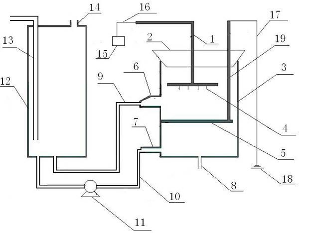
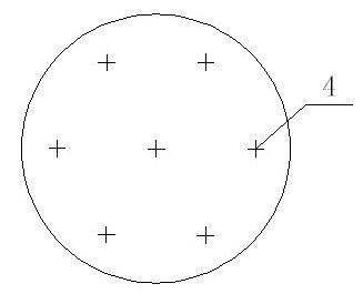
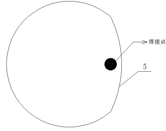
[0026] Embodiment 1: refer to figure 1 , 2 and 3, the device comprises a cylindrical reactor 3 and its bottom air inlet pipe 8, a liquid storage tank 12 and its top air outlet 14, a high-voltage electrode 4 suspended on the upper part of the reactor by fixing guide rods 1, 19 and the lower part The ground electrode 5, the external high-voltage pulse power supply 15; the top opening of the reactor is blocked with a rubber plug 2, and the opening 6 on the side wall of the reactor is connected to the liquid storage tank 12 through the liquid return pipe (liquid outlet pipe) 9, and the open The hole 6 is located between the high-voltage electrode 4 and the ground electrode 5. The opening 7 in the lower part of the side wall of the reactor is connected to the liquid storage tank 12 through the liquid inlet pipe 10, and a peristaltic pump 11 is arranged on the liquid inlet pipe; the high-voltage electrode 4 passes through the wire 16 is connected with the high-voltage pulse power s...

Embodiment 2

[0027] Embodiment 2: This device is on the basis of embodiment 1, also comprises: the material of reactor 3 is plexiglass, and internal diameter is 65mm; The diameter of the needle is 0.25mm, the distance between the needles is 15mm, and the height of the needle is 4mm. The distance between the electrode and the liquid surface is 10-30mm; the liquid storage tank 12 is provided with a sampling tube 13 extending from the top to the bottom; the reaction device is powered by a high-voltage pulse power supply 15 with a peak voltage of 46KV and a frequency of 80Hz.

Embodiment 3

[0028] Embodiment 3: refer to figure 1 , 2, 3 and 4, the method that utilizes the vapor phase high-voltage pulse discharge device of the device described in embodiment 2 to catalyze the degradation of organic dyes in water: the activated carbon fiber with a thickness of 3mm is put into a carbonization activation furnace and activated with water vapor to expand its aperture to carry out Pore ​​structure adjustment of activated carbon. During the activation process, nitrogen gas is introduced as a protective gas. When the temperature rises to 800°C, water vapor is activated for 100 minutes. The purpose of activation is to increase the specific surface area of ​​activated carbon fibers to greater than 1000m 2 / g (correspondingly increase the ratio of the pore diameter above 2nm), so that it can effectively absorb macromolecular organic matter in water while absorbing dissolved ozone in water, and react on the surface of carbon. Add 3g of activated carbon fiber into the reactor,...


PUM

PropertyMeasurementUnit
The inside diameter ofaaaaaaaaaa
Thicknessaaaaaaaaaa
Diameteraaaaaaaaaa

Abstract

The invention discloses a gas-phase high pressure pulse discharge device and a method for catalytically degrading organic dyes in water by the same. A reaction device comprises a tubular rector and a gas inlet pipe at the bottom thereof, a liquid storage tank and a gas outlet on the top thereof, a high pressure electrode and a ground electrode which are respectively hung on the upper part and thelower part of the reactor through fixed guide rods, and an external high pressure pulse power supply. Nonequilibrium plasmas generated through gas-phase high pressure pulse discharge degrade the organic dyes; and the design structure inside the reactor makes gas and liquid flowing directions fixed, can make contact time of the generated oxidative particles and pollutants prolonged, and improves the conversion efficiency of the reactor. Meanwhile, an adsorptive catalyst is put into the upper part of the reactor or into the liquid storage tank to improve the concentration of organic matters at the liquid level, so that the contact between high-activity substances and the organic matters is enhanced and the treatment efficiency can be improved. By the invention, the organic pollutants are degraded into carbon dioxide, water and nontoxic byproducts, and the invention has the advantages of high efficiency, low cost, simple process, simple operation, no secondary pollution on environment and the like.

Description

technical field [0001] The invention belongs to the non-equilibrium plasma technology in the field of environmental pollution control and a method for jointly degrading organic dyes by non-equilibrium plasma and an adsorption catalyst, in particular to a gas-phase high-voltage pulse discharge device and a method for catalytically degrading organic dyes in water. Background technique [0002] Environmental protection and water resources management have attracted great attention from the Chinese government. Revolving around the important subject of environmental protection and water treatment, relevant institutions have carried out a lot of research and application. my country is a big printing and dyeing industry country, printing and dyeing wastewater is intermittently discharged, the water quality and quantity vary widely, and the amount of wastewater discharged every year is huge. Although traditional physical methods and chemical methods have been applied in the treatment...

Claims


Application Information

Patent Timeline
IPC IPC(8): C02F1/46C02F1/74C02F1/28
Inventor 郑经堂江波杨哲吴明博李石隋吴彬张玉贞刘倩赵玉翠曲险峰刘颖
Owner CHINA UNIV OF PETROLEUM (EAST CHINA)
Learn More