High-efficiency dedusting system for high-temperature separation device of recycled cables

A technology of separation device and dust removal system, which is applied in the direction of combination device, separation method, and separation of dispersed particles, which can solve the problems of waste gas recovery and impurity removal, and achieve the effects of stable operation, efficient recovery, and enhanced efficiency

Inactive Publication Date: 2017-09-19
国网河南省电力公司西峡县供电公司
View PDF7 Cites 5 Cited by
  • Summary
  • Abstract
  • Description
  • Claims
  • Application Information

AI Technical Summary

Problems solved by technology

A hot water outlet pipe and a hot water expansion pipe are installed on the shell of the tubular heat exchanger. The hot water expansion pipe is connected to an expansion vessel, and an exhaust pipe is installed on the top of the expansion vessel. A return pipe connects a downpipe between the water tank and the shell of the heat exchanger, the flue gas travels inside the pipe, and the water is stored between the outside of the pipe and the shell, and the water absorbs the heat released by the flue gas; it still has not solved the problem The problem of waste gas recovery and impurity removal requires a dust removal device that can not only recover the waste gas, but also classify and isolate the particles in the waste gas

Method used


Image

  • High-efficiency dedusting system for high-temperature separation device of recycled cables
  • High-efficiency dedusting system for high-temperature separation device of recycled cables
  • High-efficiency dedusting system for high-temperature separation device of recycled cables

Examples


Embodiment 1

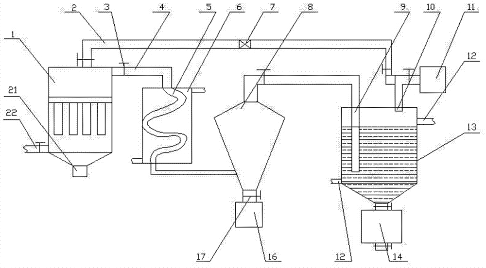
[0034] A high-efficiency dedusting system for a high-temperature separation device for recycling cables, comprising a first dedusting mechanism, an energy conversion mechanism connected to the first end of the first dedusting mechanism, and a first dedusting mechanism connected to the second end of the first dedusting mechanism. The regeneration mechanism, the settling mechanism connected with the energy conversion mechanism, the dust accumulation module arranged at the lower part of the settling mechanism, the absorbing mechanism arranged at the rear of the settling mechanism, and the discharge mechanism 11 arranged at the upper part of the absorbing mechanism , a circulation mechanism connected with the absorption mechanism, and a discharge module arranged at the lower part of the absorption mechanism;

[0035] The first dust removal mechanism includes a plurality of dust collectors 1 connected in parallel, a first air inlet pipe 22 arranged at the air inlet end of the dust c...

Embodiment 2

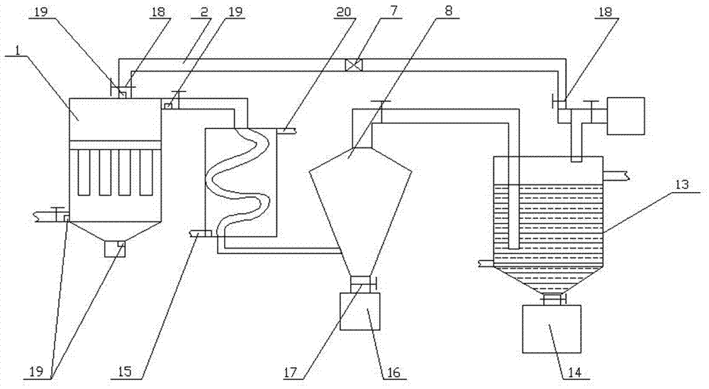
[0045] Embodiment 2, which is different from Embodiment 1 in that: the regeneration pipeline 2, the regeneration discharge pipe 21, and the first air intake pipe 22 are all equipped with a detection module 19;

[0046] The detection module 19 includes a flow rate sensor 192 , a dust sensor 191 and a temperature sensor 193 .

[0047] The first regeneration mechanism adopted in this embodiment includes a regeneration pipeline communicated with the discharge mechanism, solenoid valves arranged at both ends of the regeneration pipeline, a regeneration supercharger arranged in the middle of the regeneration pipeline, and a The regeneration discharge pipe at the lower part of the dust collector; the airflow can be pressurized by the regeneration supercharger to ensure that there is a high-speed airflow to clean the dust collector during back-blowing and dust removal, which can greatly reduce the amount of back-blowing gas and ensure The effect of overall cleaning; the energy convers...

Embodiment 3

[0048] Embodiment 3: The difference between it and Embodiment 2 is that: the first dust removal mechanism, the energy conversion mechanism, the first regeneration mechanism, the sedimentation mechanism, the dust accumulation module, the absorption mechanism, the discharge mechanism, the circulation mechanism, and the unloading module are all compatible with The signal interconnection of the control modules arranged on the outer wall of the dust collector;

[0049] The control module is PLC or personal computer.

[0050] The settling mechanism adopted in this embodiment includes a conical cylinder whose lower part communicates with the spiral tube, and the air inlet pipe is arranged in the tangential direction of the side wall of the conical cylinder, so that the airflow entering it is a helical airflow, thereby generating a high-speed swirling airflow , and as the airflow rises, due to the increase in space, large particles settle and fall into the dust accumulation module, wh...


PUM


Abstract

The invention discloses a high-efficiency dedusting system for a high-temperature separation device of recycled cables, and the dedusting system comprises a first dedusting mechanism, a transducing mechanism, a first regenerating mechanism, a settling mechanism, a dust deposition module, an absorption mechanism, an exhaust mechanism, a circulating mechanism and an unloading module, wherein the transducing mechanism is communicated with a first end of the first dedusting mechanism, the first regenerating mechanism is communicated with a second end of the first dedusting mechanism, the settling mechanism is communicated with the transducing mechanism, the dust deposition module is arranged at the lower part of the settling mechanism, the absorption mechanism is arranged at the rear part of the settling mechanism, the exhaust mechanism is arranged at the upper part of the absorption mechanism, the circulating mechanism is communicated with the absorption mechanism, and the unloading module is arranged at the lower part of the absorption mechanism. Aiming at the phenomena that the existing dedusting system cannot carry out high-efficiency utilization of waste and waste gas is exhausted into the natural environment, the mutual synergistic effect of the first dedusting mechanism, the transducing mechanism, the first regenerating mechanism, the settling mechanism, the dust deposition module, the absorption mechanism, the exhaust mechanism, the circulating mechanism and the unloading module is used, so waste gas can be efficiently recycled, and also the substances in the waste gas can be recycled.

Description

technical field [0001] The invention relates to the technical field of dust removal equipment, in particular to a high-efficiency dust removal system for a high-temperature separation device for recycling cables. Background technique [0002] Dust collector, as a dust and high-pollution industry, how to efficiently remove dust and reduce environmental pollution, and at the same time be able to extract useful compounds from the dust to realize waste utilization. At the same time, due to the shutdown of the existing dust collector If the filter is replaced or cleaned, it will affect the effect of dust removal; and for the power system, when the waste cable is recycled and separated from the furnace, a large amount of harmful gas will be generated due to incineration, and if it is directly discharged into the air, it will be harmful The air is seriously polluted, but there is no dust removal device specially designed for it in the prior art. In the authorized announcement numbe...

Claims


Application Information

Patent Timeline
Patent Type & Authority Applications(China)
IPC IPC(8): B01D50/00B01D46/00
CPCB01D50/00B01D46/70B01D50/10
Inventor 任东海赵晨封少兵包书彬孙枫淦
Owner 国网河南省电力公司西峡县供电公司
Why Eureka
Try Eureka