Wideband and wide-angle circularly polarized phased array unit

A circular polarization and phased array technology, which is applied in the direction of electrical components, antenna arrays, and radiation element structures, can solve problems such as large surface wave currents and reduce antenna radiation efficiency, so as to widen the beam width and reduce mutual coupling effects , Increase the effect of working bandwidth

Inactive Publication Date: 2017-09-29
INST OF ELECTRONICS ENG CHINA ACAD OF ENG PHYSICS
View PDF5 Cites 6 Cited by
  • Summary
  • Abstract
  • Description
  • Claims
  • Application Information

AI Technical Summary

Problems solved by technology

However, a thick substrate will bring a large surface wave current, which will greatly reduce the radiation efficiency of the antenna. At the same time, surface waves may cause scanning blind spots when scanning at large angles.
In order to suppress the scanning blind spot caused by the surface wave problem, a new microstrip antenna appears, for example, in the document IEEE Transactions on Antennas and Propagation, 1987. 35(5): p. 477- 487, author Mailloux, R.J. "On the use of metallized cavities in printed slot arrays with dielectric substrates", then designed a cavity-backed microstrip antenna, document Antenna Week, 2011: p. 1-4., author Vishwakarma, N.K., et al.'s "Design considerations for a wide scan cavity backed patch antenna for active phased array radar" designed a kind of active phased array radar antenna which combined the back cavity form and probe capacitive feeding, the antenna has the characteristics of miniaturization and wide bandwidth, at the same time, The active reflection loss is small, but the antenna is linearly polarized, which is not suitable for the widely used circularly polarized phased array antenna

Method used


Image

  • Wideband and wide-angle circularly polarized phased array unit
  • Wideband and wide-angle circularly polarized phased array unit
  • Wideband and wide-angle circularly polarized phased array unit

Examples


Embodiment 1

[0043] Simulation analysis and prototyping are carried out for the isolated antenna. The standing wave characteristics of the antenna are measured by an Agilent E5071C vector network analyzer, and the radiation characteristics of the antenna are measured in a microwave anechoic chamber.

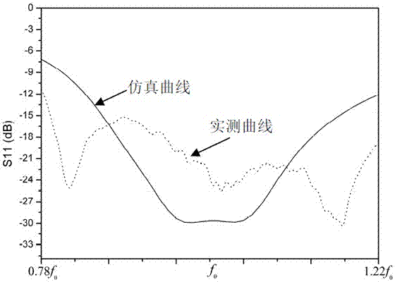
[0044] The results of the isolated antenna unit simulation and measured reflection loss S11 are as follows Figure 6 shown. The measured reflection loss S11 of the antenna is less than -10dB and the bandwidth exceeds 44%. The reason for the inconsistency between the simulated and measured curves may be caused by the reflection of objects around the test site into the measurement channel due to the wide antenna beam.

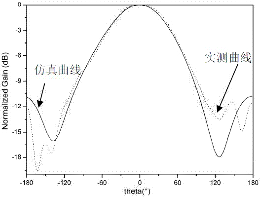
[0045] The simulation and measured radiation pattern results of the two orthogonal cut planes XZ plane and YZ plane at the center frequency of the isolated antenna element are as follows Figure 7 and Figure 8 shown. The half-beam width of the two orthogonal cut planes XZ ...

Embodiment 2

[0048] When the isolated element antenna is placed in the array, in order to achieve wide-angle scanning, the distance between the antenna elements is relatively close, and the electrical properties of the elements in the array are different from those of the isolated elements due to the influence of mutual coupling. Therefore, to measure the performance of an antenna unit, its performance in the array must be considered.

[0049] In order to evaluate the performance of the unit in the array, a 3×3 square array is designed, and a 3D simulation model is established in ANSYS HFSS and simulated. At the same time, in order to verify its simulation performance, a 3×3 square array prototype was made. In order to avoid grating lobes during wide-angle scanning in the range of ±60° in the working frequency band, the spacing between antenna elements is selected as 0.46λ0. In this embodiment, the electrical performance of the antenna is analyzed from two aspects of the mutual coupling b...

Embodiment 3

[0053] In order to verify the wide-angle scanning performance of the antenna, for an 8×8 square phased array antenna, the array simulation and measured pattern of the 8×8 square phased array antenna after scanning are shown in Figure 13 ~ Figure 15 shown.

[0054] Depend on Figure 13 ~ Figure 15 It can be seen that the antenna has good wide-angle scanning characteristics, and the measured gain at -60° is about 3.2dB lower than the normal gain. The initial relative phase of the array in the above figure is obtained by calibrating the normal direction of the antenna through the rotation vector method. Depend on Figure 15 It can be seen that when scanning at a large angle, the scanning phase shift value needs to be corrected. The antenna beam center pointing value is -54° before correction, and the antenna beam center pointing value is -60° after correction.

[0055] According to the above three embodiments, the electrical performance in the isolated state, the 3×3 array, a...


PUM


Abstract

The invention discloses a wideband and wide-angle circularly polarized phased array unit. The wideband and wide-angle circularly polarized phased array unit comprises a back cavity structure, an upper-layer dielectric substrate, a lower-layer dielectric substrate and a feeding dielectric substrate, wherein a cross microstrip patch is printed on the upper-layer substrate, two feeding points are arranged on two cross arms of the cross microstrip patch, each feeding point is provided with a capacitor feeding probe, no copper is coated on dual surfaces of the lower-layer substrate, and a Wilkinson power divider and a 90-degree phase shift microstrip line are printed on the feeding dielectric substrate. The two feeding points are respectively arranged on the two cross arms, and feeding is achieved by the Wilkinson power divider and the 90-degree phase shift microstrip line; by introducing an annular gap, a capacitance component is generated to offset an inductance component brought by the feeding of a long probe and achieve wideband matching; and by the wideband and wide-angle circularly polarized phased array unit, the beam width and the working bandwidth of an antenna can be effectively expanded, meanwhile, the mutual coupling effect during antenna array forming is reduced, so that the antenna becomes a relatively ideal circularly polarized phased array unit.

Description

technical field [0001] The invention relates to the field of phased array antennas, in particular to a wide bandwidth angle circularly polarized phased array unit. Background technique [0002] Due to its low profile, light weight, low cost and easy integration with microstrip integrated circuits, microstrip antennas have been more and more widely used in the design of array antennas. At the same time, some inherent shortcomings of microstrip antennas, such as standing waves and narrow circular polarization axis ratio bandwidth, limit its application in wide bandwidth angular scanning phased arrays. [0003] In the design of phased array antennas, it is necessary to design an antenna with a wide operating bandwidth and a large scanning angle that is easy to integrate without being limited by the shortcomings of traditional microstrip antennas. This method of widening the operating bandwidth of microstrip antennas is Use thicker microstrip substrates. In order to further br...

Claims


Application Information

Patent Timeline
Patent Type & Authority Applications(China)
IPC IPC(8): H01Q1/38H01Q1/52H01Q21/00
CPCH01Q1/38H01Q1/52H01Q1/523H01Q21/00
Inventor 崔奉云赵鹏杨春王强陈盼盼杨雷何晓阳李林翠张文涛
Owner INST OF ELECTRONICS ENG CHINA ACAD OF ENG PHYSICS
Why Eureka
Try Eureka