Mineral powder reduction system

A mineral powder and original segment technology, applied in the field of mineral powder reduction system, can solve problems such as hindering normal operation, energy consumption, water consumption, and low reduction speed, so as to improve utilization rate and system heat utilization rate, and reduce energy consumption and operating costs, and the effect of accelerating the reduction reaction rate

Pending Publication Date: 2017-10-03
SHENWU TECH GRP CO LTD
View PDF0 Cites 0 Cited by
  • Summary
  • Abstract
  • Description
  • Claims
  • Application Information

AI Technical Summary

Problems solved by technology

However, the shaft furnace method can only process massive materials, and cannot directly process powdery iron ore, and needs to be agglomerated when processing powdery iron ore, which has the disadvantages of complicated procedures, energy consumption, water consumption, and poor economy; the reaction tank method ( For example, the HyL method in Mexico) refers to that the charge is fixed in the reaction tank, and the hot reducing gas is introduced to preheat, reduce

Method used


Image

  • Mineral powder reduction system
  • Mineral powder reduction system
  • Mineral powder reduction system

Examples


Embodiment 1

[0086] Material: Iron grade of iron ore concentrate is 65%, and the proportion of iron ore powder particle size less than 0.074mm is not less than 80%;

[0087] The volume fraction of CO in the reducing gas is 80%, and the volume fraction of H2 is 15%.

[0088] Reaction conditions: The temperature of the radiation tube in the reaction zone of the iron ore powder regenerative rapid reduction device is set at 950°C.

[0089] Steps in the restore method:

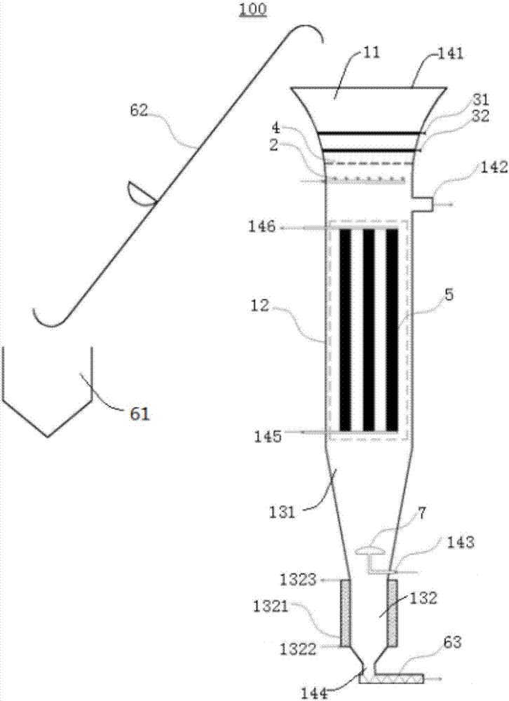
[0090] Iron ore concentrate is added to reactor 1 from feed port 141;

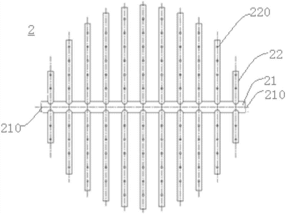
[0091] Pass the inert gas into the gas distributor 2;

[0092] The normal temperature reducing gas is introduced from the bottom of the iron ore powder regenerative rapid reduction device, and the reduction reaction is carried out with the iron concentrate;

[0093] The reducing gas is heated by the regenerative radiant tube 5 during the ascent process, exchanges heat with the falling iron ore powder and undergoes a reduction reaction, and the reduction ...

Embodiment 2

[0097] Material: the iron grade of the iron concentrate is 65%, the proportion of ore powder particles with a particle size of less than 1 mm is not less than 80%; the volume fraction of CO in the reducing gas is 60%, and the volume fraction of H2 is 30%;

[0098] Reaction conditions: The temperature of the radiation tube in the reaction zone of the iron ore powder regenerative rapid reduction device is set at 950°C.

[0099] Steps in the restore method:

[0100] Iron ore concentrate is added to reactor 1 from feed port 141;

[0101] Pass the inert gas into the gas distributor 2;

[0102] The normal temperature reducing gas is introduced from the bottom of the iron ore powder regenerative rapid reduction device, and the reduction reaction is carried out with the iron concentrate;

[0103] The reducing gas is heated by the regenerative radiant tube 5 during the ascent process, exchanges heat with the falling iron ore powder and undergoes a reduction reaction, and the reductio...


PUM

PropertyMeasurementUnit
Particle sizeaaaaaaaaaa

Abstract

The invention discloses a mineral powder reduction system, which includes: a reactor, a heating device and a gas distributor. The reactor includes a feed section, a reduction section and a cooling section. The reduction section is located below the feed section and communicates with the feed section. , the cooling section is located below the reduction section and communicates with the reduction section, the top of the feed section is provided with a feed port, the bottom of the cooling section is provided with a discharge port, and the side wall of the reactor is provided with a reduction tail gas outlet and a reduction gas inlet The heating device is arranged in the reduction section to provide heat for the reduction reaction in the reduction section; the gas distributor is arranged in the feed section, and the gas distributor has a gas inlet and an upwardly facing gas outlet, and the gas inlet and the gas outlet are connected. The gas distributor is configured to blow off the falling mineral powder in the feeding section so that the mineral powder falls into the reducing section in a dispersed manner. According to the ore powder reduction system of the embodiment of the present invention, the ore powder can be fully dispersed by the gas distributor, thereby increasing the contact area between the ore powder and the reducing gas.

Description

technical field [0001] The invention relates to the technical field of metallurgy, in particular to an ore powder reduction system. Background technique [0002] Among related technologies, the direct reduction ironmaking technology is the cutting-edge technology for the development of the iron and steel industry. 2 It is an important development direction to reduce emissions, improve the structure of iron and steel products, and improve the quality of iron and steel products. Direct reduced iron is a substitute for high-quality steel scrap, an indispensable iron source raw material for the production of high-quality pure steel, and a high-quality coolant for converter steelmaking. [0003] At present, the direct reduction methods that have reached the industrial production level or are still being tested are mainly divided into two categories: the direct reduction method using a gas reducing agent and the direct reduction method using a solid reducing agent. Among them, t...

Claims


Application Information

Patent Timeline
IPC IPC(8): C21B13/04
CPCC21B13/04C21B13/0073
Inventor 彭丽郑倩倩孟嘉乐窦从从王培伦吴道洪
Owner SHENWU TECH GRP CO LTD
Why Eureka
Try Eureka