

Conveying device used for conveying bagasse to boiler
A conveying device and bagasse technology, which is applied in supply configuration, combustion method, block/powder supply/distribution, etc., can solve the problems of reducing the thermal efficiency of the boiler, the bagasse cannot be fully burned, and the bagasse is in a piled state, so as to improve the feeding. The effect of efficiency
- Summary
- Abstract
- Description
- Claims
- Application Information
AI Technical Summary
Problems solved by technology
Method used
Image

Examples
Embodiment 1
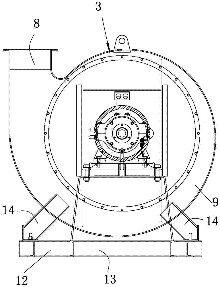
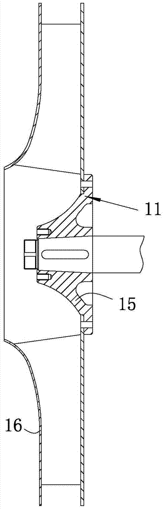
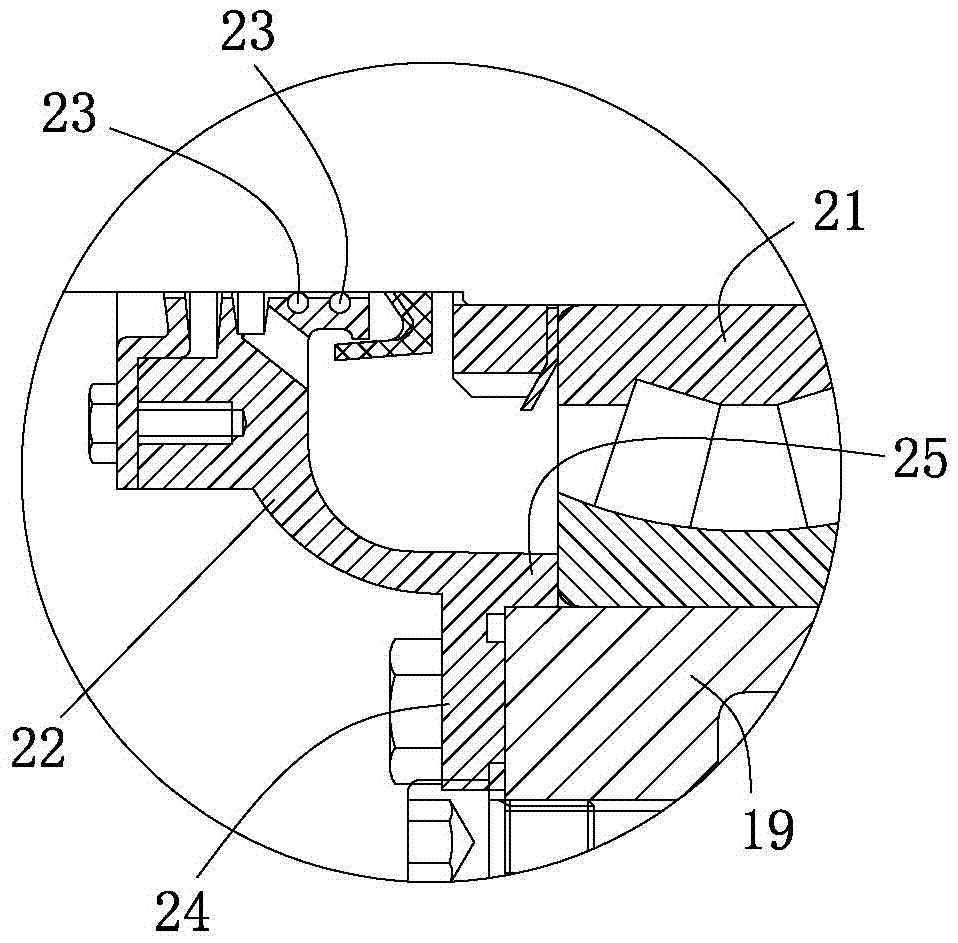
[0035] see Figure 1 to Figure 3 As shown, a conveying device for conveying bagasse to boilers according to the present invention includes a chassis 1, a support base 2 and an impeller 3 mounted on the chassis 1, and a driving motor 4 mounted on the support base 2 And the tripod 5, rotate the shaft body 6 connected to the support base 2. In this embodiment, the outer side of the shaft body 6 is provided with two rolling bearings spaced apart from each other. The two rolling bearings are installed on the support base 2. The tripod 5 is a right angle Triangular, one right-angled side of the tripod 5 is installed on the support base 2, and the other right-angled side of the tripod 5 is installed on the impeller 3, using the principle of stability of the triangle, the impeller 3 is stably positioned on the base frame 1 and the support on the seat 2 to prevent the impeller 3 from shaking during operation; the drive motor 4 drives the impeller 3 to rotate through the shaft body 6, a...
Embodiment 2
[0045] In this embodiment, the shell 9 is a metal alloy shell, and the metal alloy material for the shell is composed of the following components in weight percentage: Cr 16%, Ni 8%, Si 2%, Mn 0.6%, Ti 0.02%, Sc 0.03 %, Ce0.1%, Nb 0.02%, Mo0.02%, Cu 0.25%, P 0.02%, S 0.01%, N 0.12%, C 0.04%, and the balance is Fe.
[0046] Preferably, the preparation method of the metal alloy material for the shell comprises the following steps:
[0047] (1) Add other components except Sc and Ce according to the above ratio, and melt in a vacuum induction furnace. After all the components are melted, add a deoxidizer Ca of 0.08% by weight of the alloy melt to deoxidize the alloy melt ; Add Sc and Ce alloy melts after deoxidation, and keep stirring for 3 minutes; after standing for 2 minutes, pour the alloy melt into a casting mold to form an ingot. Alloy ingots released;
[0048] (2) Forging the alloy ingot out of the furnace at a temperature of 1050°C; then hot rolling the forged alloy ingo...
Embodiment 3
[0053] In this embodiment, the shell 9 is a metal alloy shell, and the metal alloy material for the shell is composed of the following components in weight percentage: Cr 18%, Ni 5%, Si 3%, Mn 0.2%, Ti-0.04%, Sc 0.06%, Ce0.05%, Nb 0.04%, Mo 0.01%, Cu 0.35%, P 0.01%, S 0.02%, N 0.08-0.12%, C 0.0.07%, and the balance is Fe.
[0054] Preferably, the preparation method of the metal alloy material for the shell comprises the following steps:
[0055] (1) Add other components except Sc and Ce according to the above ratio, and melt in a vacuum induction furnace. After all the components are melted, add a deoxidizer Ca of 0.15% by weight of the alloy melt to deoxidize the alloy melt. ; Add Sc and Ce alloy melts after deoxidation, and stir continuously for 5 minutes; after standing for 4 minutes, pour the alloy melt into a casting mold to form an ingot. The casting temperature is 1600 ° C. After the mold is cooled, the Alloy ingots released;
[0056] (2) Forging the alloy ingot out o...
PUM
| Property | Measurement | Unit |
|---|---|---|
| Tensile strength | aaaaa | aaaaa |
| Surface area | aaaaa | aaaaa |
Abstract
Description
Claims
Application Information