Ultra-narrow line width and wavelength adjustable composite cavity fiber laser device

A fiber laser and ultra-narrow linewidth technology, applied in the direction of lasers, laser components, phonon exciters, etc., can solve the problems of being easily disturbed by the external environment, difficult to apply on a large scale, and unsatisfactory, and achieving low cost , simple structure and reasonable structure

Active Publication Date: 2017-10-13
WUHAN UNIV OF TECH
View PDF22 Cites 7 Cited by
  • Summary
  • Abstract
  • Description
  • Claims
  • Application Information

AI Technical Summary

Problems solved by technology

[0004] The advantage of the external cavity compression method is that it can obtain laser signals with extremely narrow linewidth and high stability. The vibration mechanism is used to ensure its stability, which cannot meet the needs of communication, high-precision sensing and other applications
Fiber lasers with a ring cavity structure can obtain output with a laser linewidth of less than kilohertz, and lasers based on nonlinear effects (such as stimulated Brillouin scattering, backward Rayleigh scattering, etc.) can also obtain output with a linewidth of hundreds of Hertz. Laser output, its resonant cavity is often several meters to hundreds of meters long, very susceptible to interference from the external environment, and cannot be integrated, and it is difficult to apply on a large scale

Method used


Image

  • Ultra-narrow line width and wavelength adjustable composite cavity fiber laser device
  • Ultra-narrow line width and wavelength adjustable composite cavity fiber laser device
  • Ultra-narrow line width and wavelength adjustable composite cavity fiber laser device

Examples


Embodiment Construction

[0023] The technical solutions of the present invention will be described below in conjunction with the accompanying drawings and embodiments.

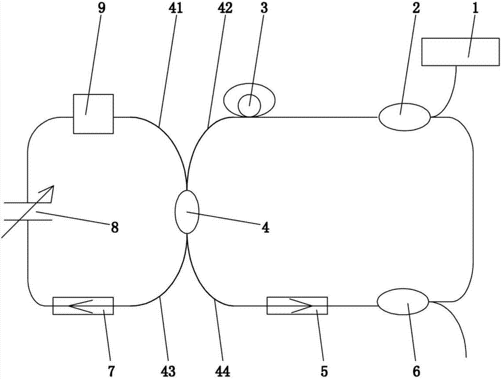
[0024] Such as figure 1 As shown, an ultra-narrow linewidth wavelength-tunable composite cavity fiber laser according to the present invention includes a pump light source 1, a wavelength division multiplexer 2, an erbium-doped fiber amplifier 3, a 2×2 fiber coupler 4, The first optical isolator 5, Y-type fiber coupler 6, tunable F-P filter 8, the second optical isolator 7 and semiconductor saturable absorber 9; the wavelength division multiplexer 2, erbium-doped fiber amplifier 3,2 The ×2 fiber coupler 4, the first optical isolator 5, and the Y-type fiber coupler 6 are sequentially connected to form a ring-shaped main resonator, in which the erbium-doped fiber amplifier 3 and the first optical isolator 5 are respectively coupled to the 2×2 optical fiber The second terminal 42 and the fourth terminal 44 of the device 4 are connected,...


PUM


Abstract

The invention relates to the technical field of laser transmitters, and specifically discloses an ultra-narrow line width and wavelength adjustable composite cavity fiber laser device. In the ultra-narrow line width and wavelength adjustable composite cavity fiber laser device disclosed by the invention, a wavelength division multiplexer, an erbium-doped optical fiber amplifier, a 2*2 optical fiber coupler, a first optical isolator, a Y-shaped optical coupler are connected in sequence to form an annular main resonant cavity; a tunable F-P filter, a semiconductor saturable absorber, a 2*2 optical fiber coupler and a second optical isolator are connected in sequence to form an annular short resonant cavity. The composite cavity fiber laser is reasonable in structure, based on a linear cavity, an annular cavity and a composite cavity fiber laser device, line width deep compression and wavelength precision tuning are carried out on fiber laser by changing the magnitude, frequency and waveform of a voltage signal applied onto the tunable F-P filter and adjusting the change state of built-in piezoelectric ceramic cavity length, so that an ultra-narrow line width and wavelength adjustable function is obtained; and the composite cavity fiber laser device has the outstanding advantages of simple structure, electromagnetic interference prevention, ultra-narrow wavelength and line width, relatively low cost and the like.

Description

technical field [0001] The invention relates to the technical field of laser emitters, in particular to a composite cavity fiber laser with ultra-narrow linewidth and adjustable wavelength. Background technique [0002] At present, an important development hot spot of fiber laser is ultra-narrow linewidth fiber laser. Existing studies have shown that single longitudinal mode ultra-narrow linewidth fiber lasers mainly have two structures: linear cavity and ring cavity. Writing fiber gratings on shorter gain fibers can produce distributed feedback gratings (DFB) and distributed Bragg reflectors (DBR) linear short-cavity fiber lasers with wider free spectral widths. By designing the gain of the gain fiber and the reflection of the grating Ratio and cavity length and other parameters can enable the laser to achieve single longitudinal mode operation, and the linewidth of the output laser can reach below 10KHz. The cavity length can also be changed by piezoelectric ceramic (PZT)...

Claims


Application Information

Patent Timeline
Patent Type & Authority Applications(China)
IPC IPC(8): H01S3/10H01S3/106H01S3/067
CPCH01S3/067H01S3/10H01S3/1067
Inventor 童杏林汪鹏飞邓承伟张翠郭倩丁磊
Owner WUHAN UNIV OF TECH
Why Eureka
Try Eureka