
Inner cavity enhanced photoacoustic spectrum type trace gas sensor device

A sensor device and trace gas technology, applied in the direction of measuring devices, instruments, scientific instruments, etc., can solve the problem of limited sensor sensitivity and achieve the effect of improving sensitivity

Inactive Publication Date: 2017-10-20
HARBIN INST OF TECH
View PDF7 Cites 21 Cited by
  • Summary
  • Abstract
  • Description
  • Claims
  • Application Information

AI Technical Summary

Problems solved by technology

[0006] An embodiment of the present invention provides a cavity-enhanced photoacoustic spectroscopy trace gas sensor device to solve the technical problem of limited sensitivity of existing sensors

Method used


Image

  • Inner cavity enhanced photoacoustic spectrum type trace gas sensor device
  • Inner cavity enhanced photoacoustic spectrum type trace gas sensor device

Examples


Embodiment 1

[0027] In photoacoustic spectroscopy, since the detection limit of the sensor is proportional to the laser power, the output power of the tunable laser is crucial to the detection performance of the sensor. However, as far as tunable lasers are concerned, the laser power output outside the laser resonator is on the order of mW (<50mW), and the acoustic wave detection element is placed outside the resonator, that is, the laser energy outside the cavity is used. This low power level of laser makes it difficult to further improve the detection performance of photoacoustic spectroscopy sensors, which cannot meet the application requirements in many fields.

[0028] However, the power level inside the laser resonator is much higher than outside the resonator. This is because the output coupling mirror of the laser has a certain transmittance. Taking the transmittance of 5% as an example, the laser power density inside the resonator is 19 times that outside the cavity. . Based on t...

Embodiment 2

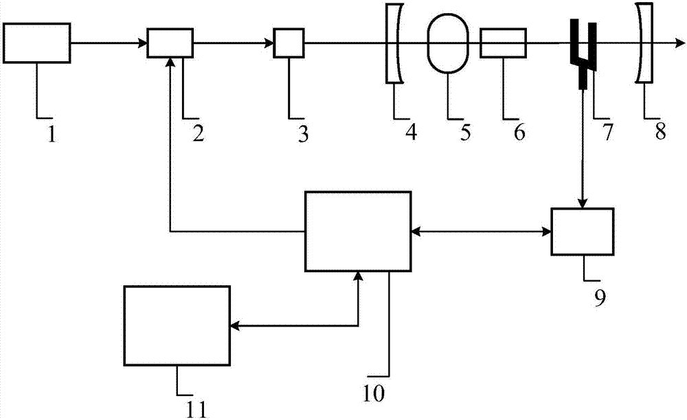
[0038] In the present invention, the target detection gas is carbon monoxide (CO) as an example, the selected absorption wavelength is 2.33 μm, the laser resonator is placed in the CO-N2 mixed gas with a concentration of 1000ppm, and the semiconductor laser modulated by the chopper passes through the The direct focusing system is incident into the laser resonator, and the tunable filter is controlled to select an oscillating laser with a wavelength of 2.33 μm to excite CO gas to generate sound waves, and the impedance amplifier is used to amplify and extract the sound wave signal detected by the quartz tuning fork. Acoustic signal strength evaluates the performance of this inner cavity photoacoustic spectroscopy gas sensor, and the technical effect is excellent.

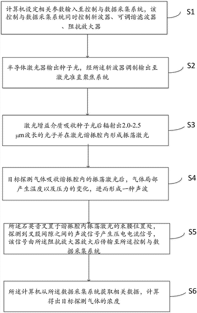
[0039] Specifically, the following steps are implemented, such as figure 2 Shown:

[0040] The relevant parameters set by the computer are input to the control and data acquisition system, and the control and data ...


PUM

PropertyMeasurementUnit
Resonant frequencyaaaaaaaaaa
widthaaaaaaaaaa
radiusaaaaaaaaaa

Abstract

The embodiment of the invention relates to the technical field of laser detection and in particular relates to an inner cavity enhanced photoacoustic spectrum type trace gas sensor device. The device comprises a semiconductor laser device, a wave chopper, a laser collimation and focusing system, a front cavity mirror, a tunable filter, a laser gain medium, a quartz tuning fork and a rear cavity mirror, which are sequentially arranged along a beam propagation direction; a piezoelectric signal generated by the quartz tuning fork is amplified by an impedance amplifier and then is transmitted to a control and data acquisition system; the control and data acquisition system is used for detecting resonance frequency of the quartz tuning fork and controlling the wave chopper in real time so that modulation frequency f is the resonance frequency f0 of the quartz tuning fork all the time; the computer is connected with the control and data acquisition system and real-time control is carried out through upper computer software Labview. The device provided by the invention can be used for rapidly detecting various types of trace gas in an atmospheric environment.

Description

technical field [0001] The invention relates to the field of laser detection, in particular to a method and equipment for detecting trace gas by using laser. Background technique [0002] There are many trace gases in the atmosphere, such as methane (CH 4 ), ozone (O 3 ), carbon monoxide (CO), etc., the concentration is on the ppt-ppm level, although their content is very low, they have a great impact on the environment. Accurately measuring the composition and content of these trace gases and their distribution changes with time and space is also of great significance for basic science and applied technology research. [0003] In the research of trace gas detection technology, measurement methods can be divided into non-spectral and spectroscopic methods. Compared with non-spectral measurement methods, spectroscopy has the advantages of high sensitivity and high resolution. At the same time, with the rapid development of laser spectroscopy technology and the advancement ...

Claims


Application Information

Patent Timeline
Patent Type & Authority Applications(China)
IPC IPC(8): G01N21/17G01N21/01
CPCG01N21/1702G01N21/01G01N2021/0106G01N2201/068
Inventor 马欲飞何应于欣李旭东彭江波杨超博闫仁鹏樊荣伟董志伟佟瑶陈德应
Owner HARBIN INST OF TECH
Learn More