Low-sidelobe antenna array based on micro-strip ridge gap waveguide unequal power divider network

A technology of power distribution feed network and gap waveguide, which is applied in the field of electronics, can solve the problems of unequal power distribution feed network and low sidelobe technology of microstrip ridge gap waveguide, and achieve easy processing integration, transmission Excellent performance and low insertion loss effect

Inactive Publication Date: 2017-10-20
NANJING UNIV OF SCI & TECH
View PDF2 Cites 32 Cited by
  • Summary
  • Abstract
  • Description
  • Claims
  • Application Information

AI Technical Summary

Problems solved by technology

[0005] It can be seen from the above that although the prior art realizes the antenna array design of the microstrip ridge gap waveguide as the feeding network, the above-mentioned articles

Method used


Image

  • Low-sidelobe antenna array based on micro-strip ridge gap waveguide unequal power divider network
  • Low-sidelobe antenna array based on micro-strip ridge gap waveguide unequal power divider network
  • Low-sidelobe antenna array based on micro-strip ridge gap waveguide unequal power divider network

Examples


Embodiment 1

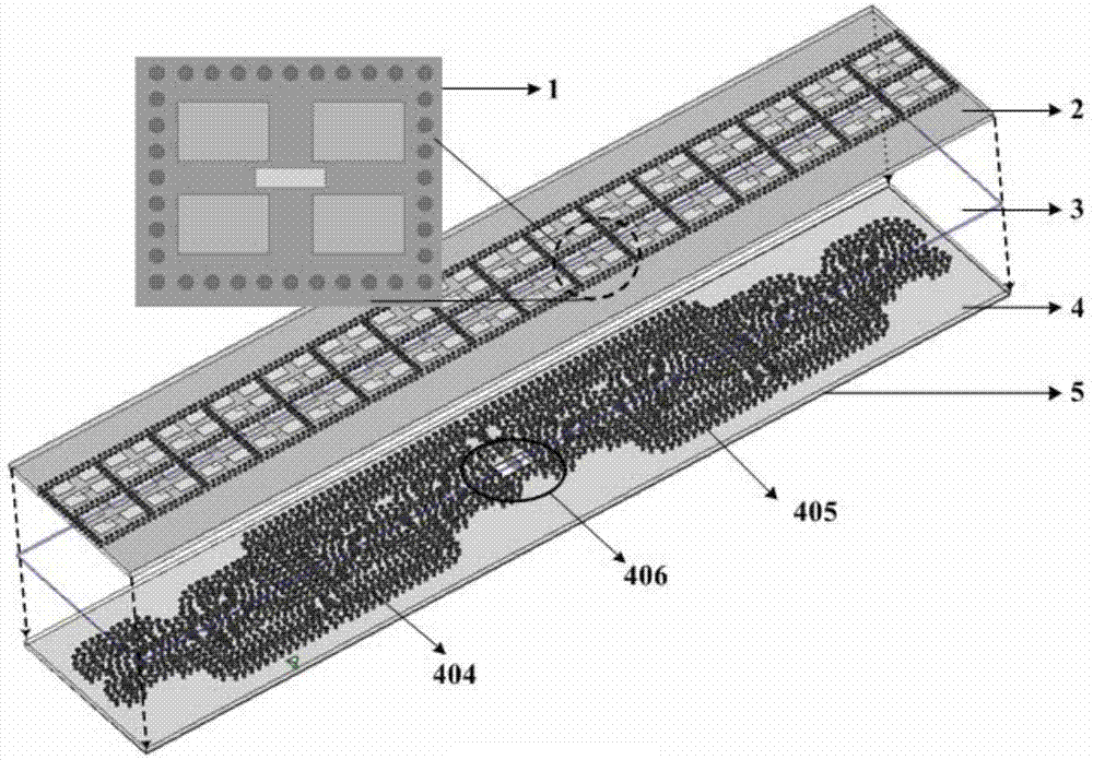
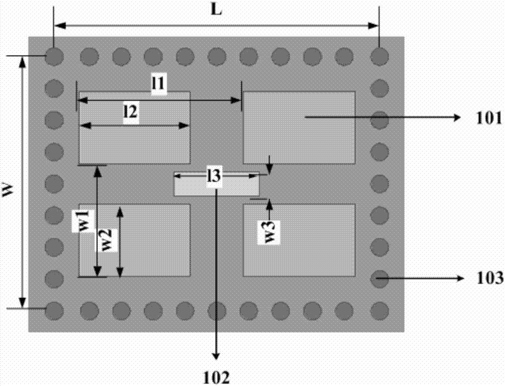
[0034] figure 1 It shows a schematic structural diagram of an embodiment of a low-sidelobe antenna array based on a microstrip ridge gap waveguide unequal power division network, including a radiation sub-array 1, a radiation layer dielectric board 2, a gap layer 3, and a feed layer dielectric board 4. Microstrip ridge 404, electromagnetic bandgap EBG 405, rectangular waveguide-GWG conversion structure 406, metal ground plane 5;

[0035] The feeding layer dielectric board 4 is arranged below the radiation layer dielectric board 2, the gap layer 3 is arranged between the radiation layer dielectric board 2 and the feeding layer dielectric board 4, and the radiation layer arranged in an array is arranged on the upper surface of the radiation layer dielectric board 2. Sub-array 1, the radiation sub-array is arranged periodically;

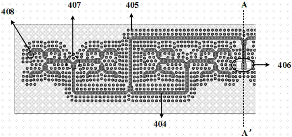
[0036] A microstrip ridge 404, an electromagnetic bandgap EBG 405, and a rectangular waveguide-GWG conversion structure 406 are arranged on the feedin...


PUM


Abstract

The invention discloses a low-sidelobe antenna array based on a micro-strip ridge gap waveguide unequal power divider network. The low-sidelobe antenna array is composed of a radiation layer dielectric plate, a gap layer, and a feeder layer dielectric plate. An electrical wall formed by plated through holes in a radiation dielectric layer and 2*2 radiation slots constitute back cavity antenna sub-arrays, and the sub-arrays are arranged periodically to form a radiation antenna array. An underlying unequal power divider network feeds power to the radiation antenna array via a coupling slot. There is an air gap of certain height between the feeder layer dielectric plate and the radiation layer dielectric plate. By using the low-sidelobe antenna array based on a micro-strip ridge gap waveguide unequal power divider network, the amplitude weighted distribution and phase matching problems of the micro-strip ridge gap waveguide unequal power divider network are solved. Moreover, the low-sidelobe antenna array has such advantages as simple structure, easy integration, simple processing, small size, wide bandwidth, low insertion loss and stable structural performance.

Description

technical field [0001] The invention relates to the field of electronic technology, in particular to a low sidelobe antenna array based on a microstrip ridge gap waveguide unequal power dividing and feeding network. Background technique [0002] For the millimeter wave band, especially the frequency band above 60 GHz, the traditional microstrip line and coplanar waveguide and other planar transmission lines will have higher insertion loss due to dispersion and loss of dielectric materials, while the traditional rectangular waveguide and coaxial transmission line in The millimeter wave band has the problems of complex machining technology, high cost, and low integration. [0003] In 2009, Professor P.-S.Kildal from Sweden published "Waveguides based on local metamaterials in the gap between parallel metal plates" on IEEE Antenna and Wireless Propagation Letters (AWPL) 2009, Vol. 8, pp. 84-87 (Local metamaterial-based waveguides in gaps between parallel metal plates)” propose...

Claims


Application Information

Patent Timeline
IPC IPC(8): H01Q1/38H01Q1/50H01Q21/00H01Q21/06
CPCH01Q1/38H01Q1/50H01Q21/0037H01Q21/0075H01Q21/061
Inventor 王昊郑玉雪曹建银季爽
Owner NANJING UNIV OF SCI & TECH
Why Eureka
Try Eureka