Sliding engagement sleeve of new energy automobile and manufacturing technique of sliding engagement sleeve

A technology of new energy vehicles and meshing sleeves, which is applied in the direction of mechanically driven clutches, mutually meshing clutches, clutches, etc., can solve the problems of difficulty in meeting the quality requirements of new energy vehicle parts, low cutting production efficiency, and insufficient tooth surface compactness. Good and other problems, to achieve the effect of improving material utilization, high production efficiency, and high mechanical properties of products

Inactive Publication Date: 2017-11-17
江苏威鹰机械有限公司
View PDF9 Cites 4 Cited by
  • Summary
  • Abstract
  • Description
  • Claims
  • Application Information

AI Technical Summary

Problems solved by technology

The existing manufacturing process of the sliding engagement sleeve: one is to select the bar and directly adopt the cutting process to produce it. The disadvantage of this process is that the production efficiency of the cutting process is low, and it is only suitable for single-piece or small-batch production applications; the other is hot forging and then cutting. The gears on the inner wall are formed. The two production processes use the traditional cutting method to form the gears on the inner wall. It is suitable for small batch production, with large capital investment in equipment, low production efficiency, low material utilization rate, long production cycle and high processing cost; secondly , the metal flow line is cut off during the cutting process, the tooth surface is not compact, the mechanical properties are poor, and it is difficult to meet the quality requirements of new energy auto parts.

Method used


Image

  • Sliding engagement sleeve of new energy automobile and manufacturing technique of sliding engagement sleeve
  • Sliding engagement sleeve of new energy automobile and manufacturing technique of sliding engagement sleeve
  • Sliding engagement sleeve of new energy automobile and manufacturing technique of sliding engagement sleeve

Examples


Embodiment

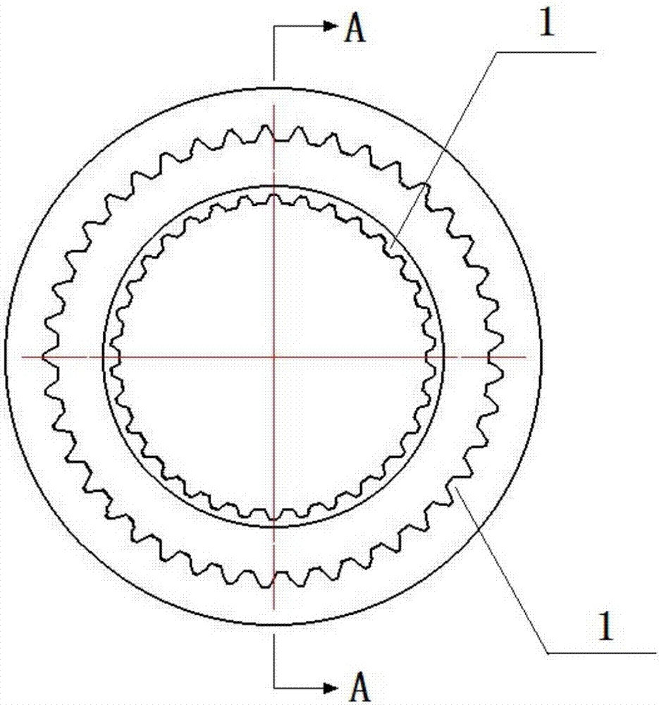
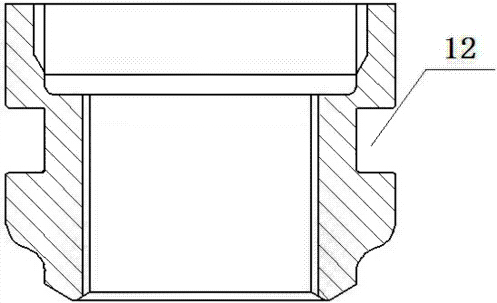
[0023] Example: see figure 1 and figure 2 As shown, a new energy vehicle sliding engagement sleeve, which is a hollow cylinder structure, the inner cavity is a structure of two cylinders with different sizes and inner diameters, and the inner wall is provided with meshing teeth 1; the outer wall corresponds to the end surface of the hollow cylinder with a small inner diameter. Shape, the outer wall is also provided with a circumferential groove 12.

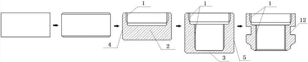
[0024] see image 3 and Figure 4 As shown, the manufacturing process of the sliding engagement sleeve for new energy vehicles includes the following steps: ①Blanking: the raw material is 20CrMnTiH, the diameter of the bar is selected, and the metal bar is cut with a circular saw; ②Spheroidizing annealing: the bar is loaded into the furnace Heating to 720°C-780°C for spheroidizing annealing, spheroidizing rate ≥ 90%, hardness ≤ 80HRC; ③ Billet making: peeling to remove surface oxide and chamfering; ④ Shot blasting: send the bi...


PUM


Abstract

The invention discloses a sliding engagement sleeve of a new energy automobile. Engaging teeth are arranged on the inner wall of a sliding engagement sleeve body, and an inner cavity of the sliding engagement sleeve body is of the structure composed of two cylinders with different inner diameters. The engaging teeth arranged on the inner wall of the sliding engagement sleeve of the new energy automobile are formed instantly by conducting cold-forging and reversed-extrusion manufacturing process twice step by step, traditional cutting machining is replaced, the production efficiency is high, raw materials are saved, and the production cost is reduced; and meanwhile, the accuracy of products is high, a extrusion-forming metal flow line is prevented from being cut off, the grain structure is compact, the strength of the toothed surface is improved, and the mechanical property and quality of the products are good.

Description

technical field [0001] The invention relates to the manufacture of a sliding engagement sleeve, in particular to a new energy vehicle sliding engagement sleeve and a manufacturing process thereof. Background technique [0002] The sliding meshing sleeve is a new energy vehicle transmission part, which has high requirements in terms of surface quality and mechanical properties. The State Intellectual Property Office discloses a sliding engagement sleeve for medium and heavy-duty vehicle drive axles. The publication number is CN205244173U. The tooth surfaces of the teeth are distributed in the shape of high and low steps, and the tooth sides of the meshing teeth are increased with a drum shape. The sliding engagement sleeve reduces the contact area between the sliding engagement sleeve and the fixed engagement sleeve tooth surface, so that the area of ​​the oil film adhesion between the two is also reduced correspondingly, which effectively solves the problems caused by the s...

Claims


Application Information

Patent Timeline
Patent Type & Authority Applications(China)
IPC IPC(8): F16D11/16B21C25/02B21C23/20
CPCF16D11/16B21C23/20B21C25/02F16D2011/002
Inventor 张太良万永福
Owner 江苏威鹰机械有限公司
Why Eureka
Try Eureka