
Wall flow type particle filter carrier coating method adopting organic sol

A particle filter and organosol technology, applied in chemical instruments and methods, separation methods, coatings, etc., can solve problems such as limited cost, catalyst coating difficulties, catalyst structure, atomic ratio and adverse effects of catalytic effects, etc. achieve the effect of promoting stability

Inactive Publication Date: 2017-11-21
CHINA FIRST AUTOMOBILE
View PDF2 Cites 6 Cited by
  • Summary
  • Abstract
  • Description
  • Claims
  • Application Information

AI Technical Summary

Problems solved by technology

However, the problem of DPF regeneration has always troubled users and OEMs. Active / passive regeneration requires additional energy, which increases costs and creates additional burdens.
[0004] The most commonly used catalysts are noble metals, but wall-flow particulate filters using noble metal catalysts are severely limited by cost. Composite metal oxide catalysts such as perovskites have been proven to be able to achieve catalytic oxidation of particulate matter in the exhaust gas atmosphere, among which Especially the catalytic performance of composite metal oxides containing potassium is outstanding
However, the coating of catalysts containing potassium is more difficult
Generally, the catalyst sol containing potassium is used to impregnate the wall-flow particle filter carrier, but it is found that due to the K + Very soluble in water, this method will adversely affect the structure, atomic ratio and catalytic effect of the catalyst after coating

Method used


Image

  • Wall flow type particle filter carrier coating method adopting organic sol
  • Wall flow type particle filter carrier coating method adopting organic sol
  • Wall flow type particle filter carrier coating method adopting organic sol

Examples


Embodiment 1

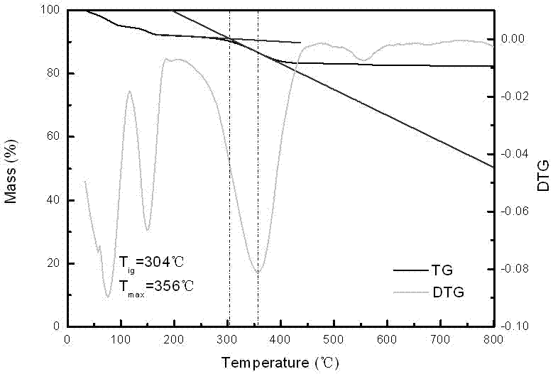
[0022] Embodiment 1 (comparative example)

[0023] A 200-mesh cordierite wall-flow particle filter was selected as the test object, and processed in the following order:

[0024] A) Put the wall-flow particle filter in the alumina sol with a solid content of 6% for 2 hours, take it out, drain the excess alumina sol in the DPF carrier channel, and bake it at 400°C for 2 hours to form α-Al2O3 coating covered Wall flow particulate filter.

[0025] B) The catalyst is a potassium-containing perovskite catalyst La 0.9 K 0.1 FeO 3 (The molar ratio of potassium element in the catalyst metal is 5%). The particle size of the catalyst is controlled below 3 μm by ball milling. Surfactant PVP and stirring are used to promote the dispersion of the catalyst. The solid content of the catalyst is 4%.

[0026] C) Immerse the α-Al2O3 coated wall-flow particle filter obtained in step A) into the suspension obtained in step B) and keep it for 1 hour; take it out, and use compressed air to blow...

Embodiment 2

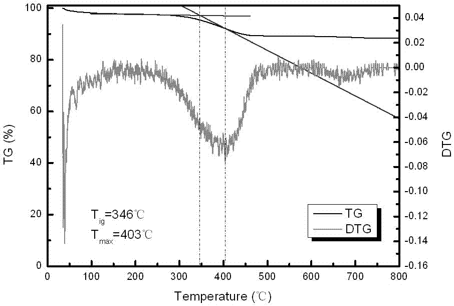
[0030] A 200-mesh cordierite wall-flow particle filter was selected as the test object, and processed in the following order:

[0031] A) Put the wall-flow particle filter in the alumina sol with a solid content of 6% for 2 hours, take it out, drain the excess alumina sol in the DPF carrier channel, and bake it at 400°C for 2 hours to form α-Al2O3 coating covered Wall flow particulate filter.

[0032] B) Preparation of potassium-containing perovskite catalyst La 0.9 K 0.1 FeO 3 (The molar ratio of potassium element in the catalyst metal is 5%) suspension, the first component adopts 2-butanone, and the second component is the selected catalyst, La 0.9 K 0.1 FeO 3 , the third component uses the polymer shown in (I) (m=100, n=20, R 1 =R 2 =H, x=y=2), the mass ratio of the three is 88:12:0.6, and the particle size of the catalyst is controlled below 3 μm by ball milling.

[0033]C) Immerse the α-Al2O3 coated wall-flow particle filter obtained in step A) into the suspension...

Embodiment 3

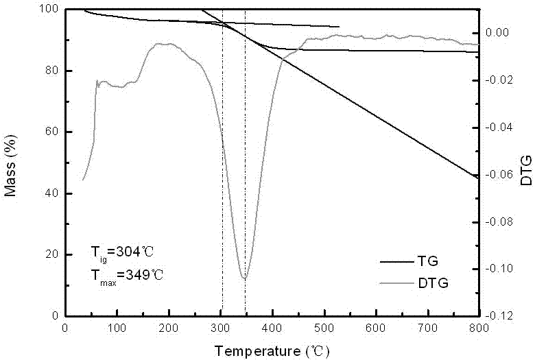
[0037] A 200-mesh cordierite wall-flow particle filter was selected as the test object, and processed in the following order:

[0038] A) Put the wall-flow particle filter in the alumina sol with a solid content of 6% for 2 hours, take it out, drain the excess alumina sol in the DPF carrier channel, and bake it at 400°C for 2 hours to form α-Al2O3 coating covered Wall flow particulate filter.

[0039] B) Preparation of potassium-containing perovskite catalyst La 0.6 K 0.4 FeO 3 (The molar ratio of potassium element in the catalyst metal is 20%) suspension, the first component adopts xylene, the second component is the selected catalyst, La 0.6 K 0.4 FeO 3 , the third component uses the polymer shown in (I) (m=1000, n=200, R 1 =R 2 =CH 3 , x=y=10), the mass ratio of the three is 96:4:0.04, and the particle size of the catalyst is controlled below 3 μm by ball milling.

[0040] C) Immerse the α-Al2O3 coated wall-flow particle filter obtained in step A) into the suspensi...


PUM


Abstract

The invention relates to a wall flow type particle filter carrier coating method adopting organic sol. The method is characterized by comprising the following steps that a wall flow type particle filter is arranged in aluminum oxide sol and roasted after being taken out, and the wall flow type particle filter covered with an alpha-Al2O3 coating is formed; in the step A, suspension liquid containing a potassium element catalyst is prepared; in the step B, the wall flow type particle filter covered with the alpha-Al2O3 coating and obtained in the step A is immersed in the suspension liquid obtained in the step B; after standing is conducted for a period of time, the wall flow type particle filter is conducted, residual suspension liquid hanging to the surface is removed, drying is conducted, and after roasting, the wall flow type particle filter coated with the potassium element catalyst is obtained. For the current situation that a wall flow type particle filter coated with water-series catalyst suspension liquid can generate adverse influences on the catalysis effect of the catalyst, the copolymer of the methacrylic acid derivative is adopted as the surface active agent, the catalyst suspension liquid is stabilized, stabilization of the suspension liquid is promoted, and accordingly it is guaranteed that after coating of the catalyst, the original catalysis effect of the catalyst is still kept.

Description

technical field [0001] The invention relates to a method for coating a carrier of a wall-flow particle filter using organic sol, which belongs to the field of gas treatment containing particulate matter, in particular to the field of treatment of exhaust gas from heat engines containing particulate matter, including diesel engines, diesel generators, boilers, etc. Treatment of particulate exhaust gas; especially suitable for the case where the catalyst is a potassium-containing system metal oxide. Background technique [0002] Due to insufficient combustion, the exhaust gas of diesel engines, diesel generators, boilers, etc. contains a large amount of particulate matter, which has brought serious environmental pollution. Wall flow particulate filter (DPF) can effectively filter particulate matter. Or the country VI stage, it is bound to be widely used. However, the problem of DPF regeneration has always troubled users and OEMs. Both active and passive regeneration need to p...

Claims


Application Information

Patent Timeline
Patent Type & Authority Applications(China)
IPC IPC(8): B05D1/18B05D7/24B05D3/02B01D53/94
CPCB01D53/94B05D1/185B05D3/0254B05D7/24
Inventor 王丹张苡铭赵中令张喆常潇然张克金
Owner CHINA FIRST AUTOMOBILE
Learn More