Stainless steel photoelectrochemical reaction device with both online and offline gas analysis functions
A chemical reaction and offline analysis technology, applied in the field of new stainless steel photoelectrochemical reaction devices, can solve the problems of fragile, expensive glass pipes, complicated stainless steel pipe connection process, etc., to improve accuracy and reliability, avoid solution heating and Thermal evaporation, avoiding the effect of solution heating and evaporation
- Summary
- Abstract
- Description
- Claims
- Application Information
AI Technical Summary
Problems solved by technology
Method used
Image
Examples
Embodiment 1
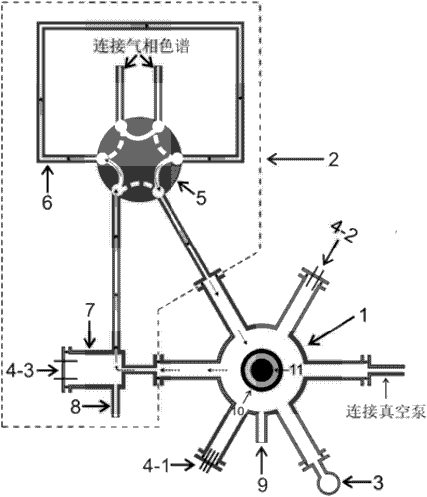
[0041] 1. A photoelectrochemical reaction device with both on-line and off-line gas analysis functions, mainly composed of a main reaction chamber, a gas circulation loop and a circulating water cooling system (see figure 1 shown). The gas flow direction in the reaction device is as follows: figure 1 indicated by the dotted arrow.
[0042] Specifically, the components of the device are as follows:
[0043] (1) Main reaction chamber: the main structure is a stainless steel 9-way chamber, 2 flanges are located on the upper and lower parts respectively, 6 flanges are located in the middle of the main reaction chamber and are distributed at 60 degrees, and 1 ferrule is welded in the middle of the chamber. An optical window is connected to the main reaction chamber through a flange on the upper part of the main reaction chamber. A photoelectrochemical electrolytic cell with a three-electrode system is sealed in the main reaction chamber. In the test, the light shines on the ph...
Embodiment 2
[0064] Embodiment 2 The effect of circulating water cooling device
[0065] During the photoelectrochemical reaction process, it is necessary to use a high-power light source to illuminate the photoelectrode. The temperature rise of the solution due to light will bring the following adverse effects:
[0066] 1) The temperature of the photoelectrochemical reaction changes with the light time;
[0067] 2) The solution evaporates rapidly due to heating up, so that the concentration of the solution changes significantly;
[0068] 3) Evaporated water condenses on the optical window, changing the intensity of the light.
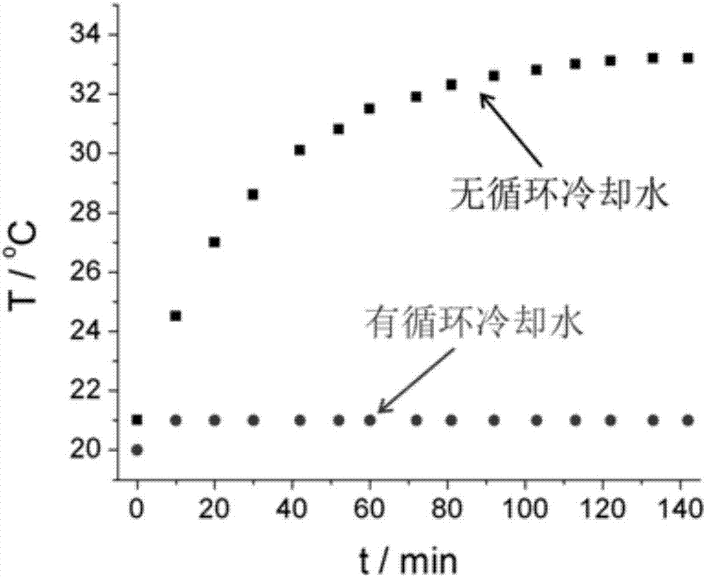
[0069] By using a thermocouple, it is possible to measure the temperature of the solution in the electrolytic cell as a function of the exposure time. like figure 2 As shown, the temperature of the solution increased from 20 °C to 33.2 °C after 140 min of irradiation. At the same time, the solution in the electrolytic cell was reduced by about 2 ml (about 10%...
Embodiment 3
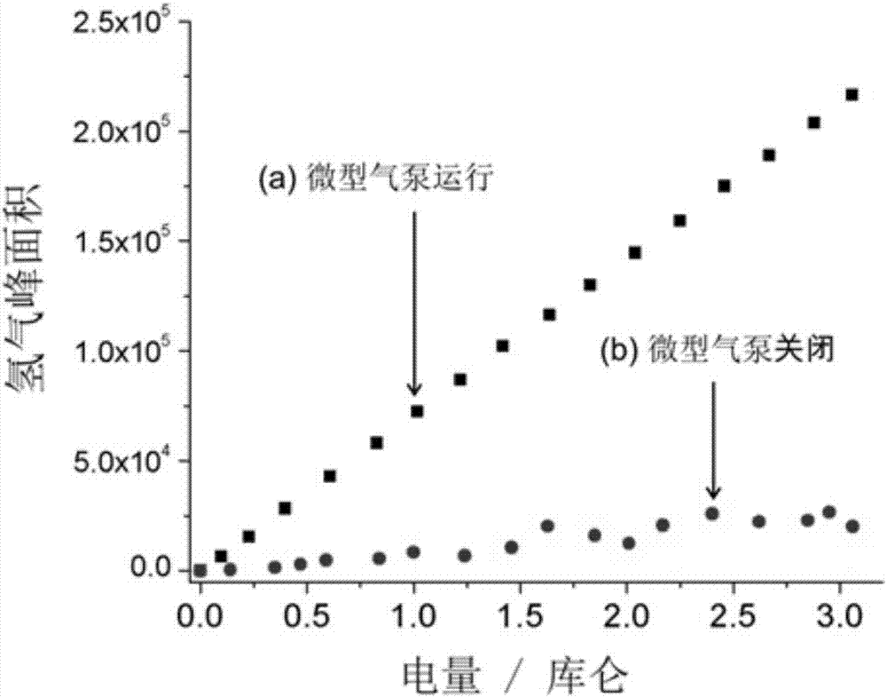
[0071] Embodiment 3 The relationship between the amount of calibration hydrogen and the hydrogen peak area measured by gas chromatography
[0072] 1. Experimental method
[0073] (1) Mix 20 ml of 0.1 mol / L Na 2 SO 4 The solution is poured into the electrolytic cell. Use a platinum wire with a diameter of 0.5 mm as the working electrode, a large-area platinum sheet as the counter electrode and an Ag / AgCl / Cl - as a reference electrode. After the three electrodes are connected to the electrode terminals, the electrolytic cell is sealed in the main reaction chamber.
[0074] (2) Rotate the switch of the six-way valve to connect the quantitative sampling loop to the main reaction chamber.
[0075] (3) Turn on the vacuum pump and fill it with argon to completely replace the gas inside the reactor. After the replacement is completed, turn off the vacuum pump and replace the gas.
[0076] (4) Turn on the micro air pump and keep it running during the reaction.
[0077] (5) Turn...
PUM
 Abstract
Description
Claims
Application Information
 - R&D
- Intellectual Property
- Life Sciences
- Materials
- Tech Scout
- Unparalleled Data Quality
- Higher Quality Content
- 60% Fewer Hallucinations
Browse by: Latest US Patents, China's latest patents, Technical Efficacy Thesaurus, Application Domain, Technology Topic, Popular Technical Reports.
© 2025 PatSnap. All rights reserved.Legal|Privacy policy|Modern Slavery Act Transparency Statement|Sitemap|About US| Contact US: help@patsnap.com


