

Cambered surface machining machine tool based on laser positioning
A technology for laser positioning and processing machine tools, applied in metal processing equipment, grinding machine parts, grinding machines, etc., can solve the problems of easy machine shaking, insufficient linear adjustment, easy processing errors, etc., to achieve difficult processing errors, cost saving, The effect of linearization of the height adjustment process
- Summary
- Abstract
- Description
- Claims
- Application Information
AI Technical Summary
Problems solved by technology
Method used
Image

Examples
Embodiment
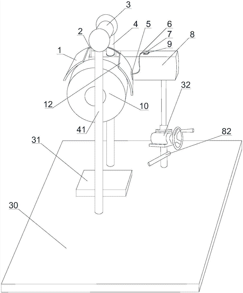
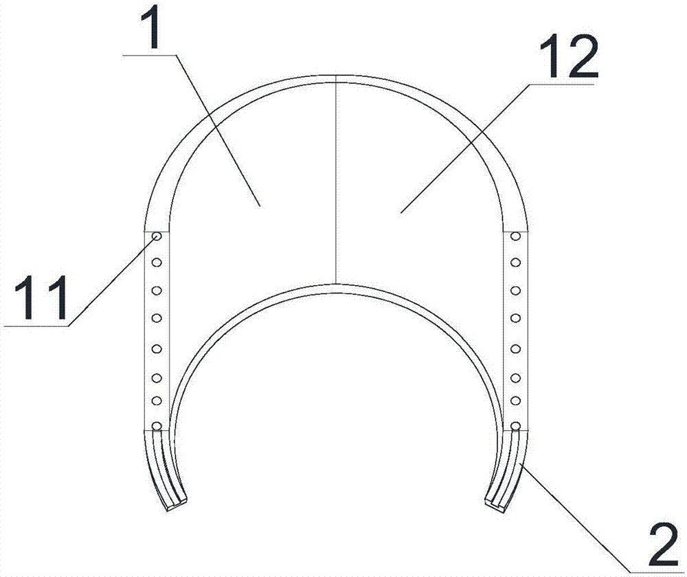
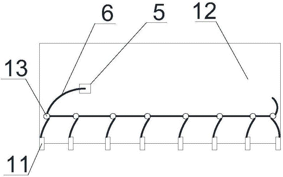
[0032] Such as Figure 1~4As shown, the arc surface processing machine tool based on laser positioning includes a grinding machine 8, a grinding wheel 10, a track 2, a bottom plate 30, a stage 31, a main pillar 4, an auxiliary pillar 41, a beam 3 and a worm gear lifter 32, and the grinding wheel 10 is installed On the side of the mill 8 , the rotating shaft of the grinding wheel 10 is perpendicular to the side of the mill 8 and parallel to the horizontal plane, and the track 2 is fixed on the mill 8 . The main pillar 4 and the auxiliary pillar 41 are vertically fixed on the base plate 30, the two ends of the beam 3 are respectively connected with the tops of the main pillar 4 and the auxiliary pillar 41 to form a gantry structure, and the mill 8 is slidingly connected to the main pillar 4; The base of 32 is fixed on the base plate, and its lifting screw mandrel top is connected with mill 8, and electric lamp 82 is housed on the base of worm gear lifter 32.
[0033] Also inclu...
PUM
 Abstract
Description
Claims
Application Information