
Joint heat regenerative system

A heat recovery system and heat exchanger technology, applied in preheating, feed water heaters, lighting and heating equipment, etc., can solve problems such as heat loss, low-temperature condensation of equipment, black smoke from fuel, etc., to alleviate equipment blockage, Achieve the effect of drying output and increasing the temperature of feed water

Pending Publication Date: 2017-11-24
冯煜珵
View PDF1 Cites 3 Cited by
  • Summary
  • Abstract
  • Description
  • Claims
  • Application Information

AI Technical Summary

Problems solved by technology

It takes about 8-10 hours for a traditional thermal power generating set to start from ignition to grid connection. During this period, a large amount of steam is sent to the condenser through the bypass system. Although the working fluid is recovered, the heat is lost.
In addition, there are still problems such as low pulverized coal combustion rate, black smoke from fuel oil, and air preheater in the tail flue, which are prone to low-temperature condensation, ash blocking, and corrosion during the start-up phase.

Method used


Image

  • Joint heat regenerative system
  • Joint heat regenerative system
  • Joint heat regenerative system

Examples


Embodiment 1

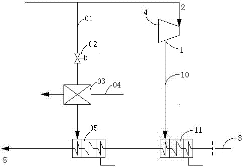
[0051] figure 1 It is a schematic diagram of the system of the specific embodiment 1 of the present invention. In this embodiment, on the basis of the conventional final steam extraction port 1, the conventional final steam extraction 10, the conventional final feed water heater 11, and the main steam pipeline 2, additional An additional pipeline 01, a steam side regulating valve 02 on the additional pipeline, a heat exchanger 03, and an additional adjustable rear feedwater heater 05 are provided.

[0052] The additional adjustable post-final feedwater heater 05 is connected to the heat exchanger 03 and the main steam pipeline 2 through the additional pipeline 01, and the steam side regulating valve 02 is set in the additional pipeline 01 between the main steam pipeline 2 and the heat exchanger 03 superior. The steam side regulating valve 02 is used to regulate the main steam in the additional pipeline 01, and the feedwater temperature at the outlet of the additional adjustab...

Embodiment 2

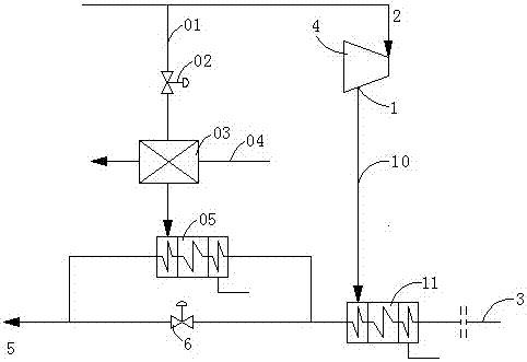
[0057] figure 2 It is a schematic diagram of the system of the specific embodiment 2 of the present invention. In this embodiment, on the basis of the conventional final steam extraction port 1, the conventional final steam extraction 10, the conventional final feed water heater 11, and the main steam pipeline 2, an additional An additional pipeline 01, a steam side regulating valve 02 on the additional pipeline, a heat exchanger 03, an additional adjustable rear feedwater heater 05, and a water side regulating valve 6 are provided.

[0058] The main difference between this embodiment and Embodiment 1 is that a water-side regulating valve 6 is added, which is connected in parallel with the additional adjustable final feedwater heater 05. Therefore, the additional adjustable rear final feedwater heater 05 can be designed as a part capacity feedwater heaters, reducing heater costs.

[0059] The only difference between the usage method of the system of this embodiment and that ...

Embodiment 3

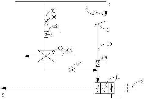
[0061] image 3 It is a schematic diagram of the system of the specific embodiment 3 of the present invention. This embodiment adds additional Pipeline 01, steam side regulating valve 02 on the additional pipeline, heat exchanger inlet isolating valve 06, heat exchanger outlet isolating valve 07, heat exchanger 03.

[0062] The main difference between this embodiment and Embodiment 1 is that no additional adjustable rear feedwater heater 05 is added. The steam pipeline passing through the heat exchanger is directly sent to the original conventional final stage feed water heater 11 . Its advantage is that it saves an additional adjustable post-final feedwater heater 05, which reduces investment, and it can completely recover the steam heat that would have been wasted through the bypass system in the start-up stage of the unit, just like Example 1. On the other hand, the original conventional final stage feed water heater 11 can also be used to supplement and heat the feed wat...


PUM


Abstract

The invention discloses a joint heat regenerative system which comprises a high-pressure cylinder of a steam turbine, a main steam pipeline, a conventional last-stage steam extraction pipeline, an additional pipeline, heat exchangers, a feed water heater and a steam-side adjusting valve. The additional pipeline is additionally arranged on the main steam pipeline, main steam in the main steam pipeline is used as a heat source for the heat exchangers, exhausted steam of the heat exchangers is used as a heat source for the feed water heater, and the steam-side adjusting valve is arranged on the additional pipeline and is used for adjusting main steam in the additional pipeline, so that steam extraction pressures adjusted by the steam-side adjusting valve can be controlled, outlet temperatures of the feed water heater can be controlled, and requirements on ultimate feed water temperatures can be met. The joint heat regenerative system has the advantages that heat of steam of boilers can be recycled at starting phases of units by the aid of the joint heat regenerative system, and the problems of low pulverized coal burnout rates, black smoke of fuel oil and easiness in low-temperature moisture condensation, ash clogging, corrosion and the like of equipment such as air preheaters of tail flues in starting phases can be solved by the aid of the joint heat regenerative system.

Description

technical field [0001] The invention relates to the field of thermal power generation, in particular to a combined heat recovery system. Background technique [0002] At present, my country's electricity is mainly undertaken by thermal power generation units for peak regulation, and low-load operation of thermal power generation units has become the norm. With the official release of my country's "Thirteenth Five-Year Plan for Electric Power Development (2016-2020)", "strengthening peak peak capacity building and improving system flexibility" has become one of the important tasks of thermal power generating units, which means that the thermal power The deep peak shaving and system flexibility of the generating set put forward higher requirements. In fact, the thermal power generating set operates at low load, and there are many problems such as environmental protection, safety, and economy, including the need to withdraw the operation of the SCR denitrification device, the bo...

Claims


Application Information

Patent Timeline
Patent Type & Authority Applications(China)
IPC IPC(8): F22D1/32F01K11/02
CPCF01K11/02F22D1/325F01K7/40F01K7/36F01K7/44F22D1/36F01K7/22F01K13/02F05D2220/31
Inventor 冯煜珵
Owner 冯煜珵
Learn More