Supersonic swirling capture treatment system for flue gas

A processing system, supersonic technology, applied in separation methods, dispersed particle separation, chemical instruments and methods, etc., can solve the problems of high investment cost, large greenhouse gas, large floor space, etc., and achieve low energy consumption and large processing capacity. , the effect of prolonging the service life

Active Publication Date: 2017-11-28
SOUTHWEST PETROLEUM UNIV +1
View PDF6 Cites 5 Cited by
  • Summary
  • Abstract
  • Description
  • Claims
  • Application Information

AI Technical Summary

Problems solved by technology

Conventional treatment methods often use adsorption and condensation to dry flue gas, which covers a large area, the process is relatively complicated, and the investment cost is high
In addition, the flue gas contains a large amount of CO2. Even after desulfurization, denitrification and dehydration, there is still a large amount of CO2. If it is directly discharged into the atmosphere, it will cause greenhouse A large amount of gas is emitted. At present, conventional methods such as membrane method and low-temperature separation method are used to treat CO2, which is costly and complicated.

Method used


Image

  • Supersonic swirling capture treatment system for flue gas
  • Supersonic swirling capture treatment system for flue gas
  • Supersonic swirling capture treatment system for flue gas

Examples


Embodiment 1

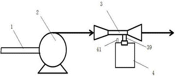
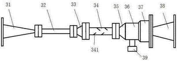
[0023] A supersonic cyclone capture and treatment system for flue gas, comprising a flue gas pipeline 1 , a compressor 2 , a cyclone separation pipe 3 and a collection device 4 . One end of the flue gas pipe 1 is connected to the flue gas pipe of the production system, the other end is connected to the inlet of the compressor 2, the outlet of the compressor 2 is connected to the inlet of the cyclone separation pipe 3, and the cyclone separation pipe 3 includes a jet expansion section, a swirl separation section and a diffusion deceleration section. The jet expansion section includes a first tapered pipe 31 and a first straight pipe 32. The large end of the first tapered pipe 31 is connected to the compressor 2 Outlet flange connection; the small end of the first tapered pipe 31 is flanged to one end of the first straight pipe 32, and the cyclone separation section includes a second tapered pipe 33, a second straight pipe 34 and a second straight pipe 34. The third composite pi...

Embodiment 2

[0034] The flue gas treated in the first stage is stripped of moisture, but the gas contains a large amount of CO 2 , if discharged directly into the atmosphere, it will lead to a large amount of greenhouse gas emissions. CO 2 Captured, stored or rationally utilized, can greatly reduce carbon emissions and achieve CO 2 Turning waste into wealth, so the supersonic swirl capture and treatment system of flue gas can be used to treat CO 2 Perform capture processing.

[0035] 1. Use the compressor 2 to increase the pressure of the flue gas treated in Example 1 to 10 MPa, so as to provide power for the next step of the flue gas to enter the cyclone separation pipe. After the flue gas is pressurized, a pressure difference is formed before and after the first conical tube to allow the gas to flow. The greater the pressure difference, the greater the gas velocity. After passing through the injection expansion section, the temperature drops more (expansion refrigeration), normal pres...


PUM


Abstract

The invention discloses a supersonic swirling capture treatment system for flue gas. The system consists of a flue gas pipeline, a compressor, a hydrocyclone separation pipe and a collection device. One end of the flue gas pipeline is connected to a flue gas pipeline of a production system, and the other end is connected to the compressor inlet, the compressor outlet is connected to the inlet of the hydrocyclone separation pipe, the hydrocyclone separation pipe includes a jet expansion section, a hydrocyclone separation section and a diffusion deceleration section, and the collection device is arranged below a water outlet to collect condensate liquid. Compared with the prior art, according to the supersonic swirling capture treatment system for flue gas provided by the invention, flue gas is pressurized and accelerated and then jetted into the hydrocyclone separation pipe, hydrocyclone separation is carried out to realize stripping of moisture in flue gas, and separation and storage of carbon dioxide in the flue gas can be realized. The system has the advantages of small land occupation, easy operation, large treatment capacity, low energy consumption, convenient maintenance, etc.

Description

technical field [0001] The invention relates to the field of environmental equipment, in particular to a system for capturing and treating flue gas. Background technique [0002] With the development of society, environmental protection has increasingly become the focus of everyone's attention, and the treatment of flue gas emissions in industrial production has always been the focus of everyone's research. Because flue gas components are generally nitrogen, carbon dioxide, water vapor, oxygen, trace amounts of sulfur dioxide and nitrogen oxides, if a large amount of flue gas is directly discharged into the atmosphere, it will have a serious impact on the environment. If the flue gas is captured and used reasonably, it can turn waste into wealth and contribute to environmental protection. After the flue gas is sorted and collected, it can be used for oil recovery. Combining the advantages of nitrogen and carbon dioxide to increase production, the effect of improving oil rec...

Claims


Application Information

Patent Timeline
Patent Type & Authority Applications(China)
IPC IPC(8): B01D45/16B01D53/18
CPCB01D45/16B01D53/1475B01D53/18
Inventor 付万春李东元齐东明赵红蕾
Owner SOUTHWEST PETROLEUM UNIV
Why Eureka
Try Eureka