
High-speed structured light scanning method and system based on stereo vision

A technology of stereo vision and scanning method, applied in the direction of using optical devices, instruments, measuring devices, etc., can solve the problems of large amount of information, limited scanning speed, limited resolution, etc., to increase image resolution and improve detection speed. , the effect of improving the detection accuracy

Active Publication Date: 2021-04-13
北京高铁达安科技有限公司
View PDF5 Cites 0 Cited by
  • Summary
  • Abstract
  • Description
  • Claims
  • Application Information

AI Technical Summary

Problems solved by technology

However, in the case of single-beam light scanning used for measurements such as on-board rail detection, the light intensity is limited, so the resolution of the collected light band images is limited; in addition, under the same hardware facilities, the acquisition and processing module The processing speed is limited to a certain extent, and the output frequency of the camera is difficult to be greatly improved, so the scanning speed is limited to a certain extent, resulting in the limitation of the data acquisition and processing frequency.
In this case, it will be difficult to further increase the detection speed, making it difficult to further improve the quality of structured light scanning detection
Changing the hardware facilities, such as using the high-speed stereo camera in the prior art to collect the outline information and information processing of the object to be scanned, will greatly increase the cost of the equipment, and due to the huge amount of image information collected by the high-speed stereo camera, it is necessary to process information The huge amount will also greatly affect the scanning detection rate, resulting in a decline in the quality of structured light scanning detection

Method used


Image

  • High-speed structured light scanning method and system based on stereo vision
  • High-speed structured light scanning method and system based on stereo vision
  • High-speed structured light scanning method and system based on stereo vision

Examples


Embodiment Construction

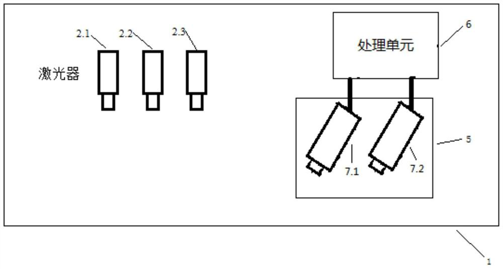
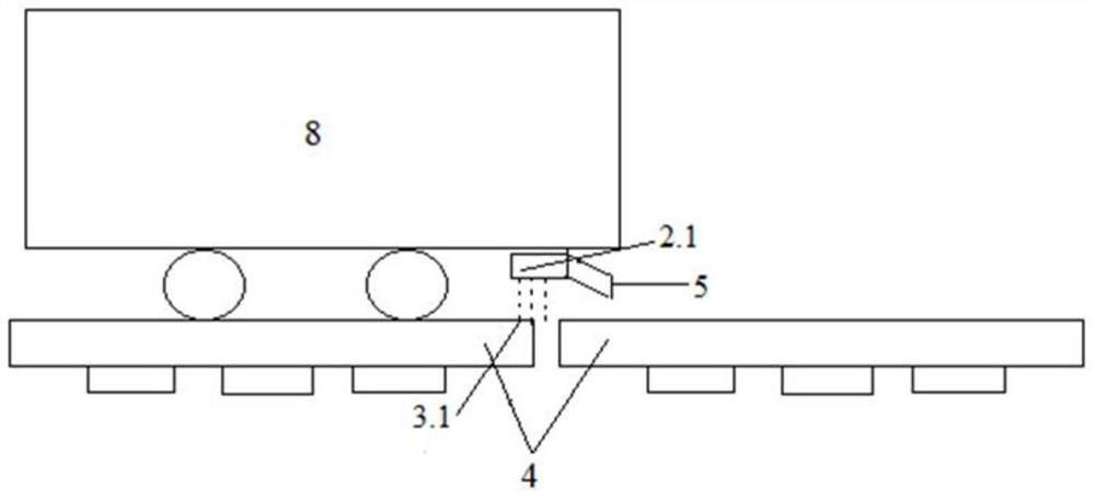
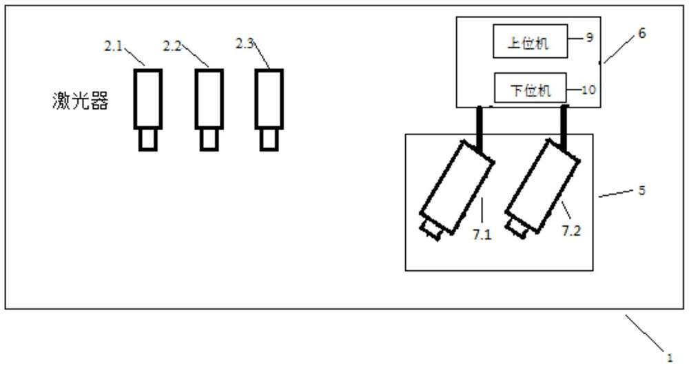
[0042] In order to make the purpose, technical solution and advantages of the present invention clearer, the present invention will be further clearly described in detail below through specific embodiments and in conjunction with the accompanying drawings. Those skilled in the art should understand that the described specific implementations are only for the purpose of illustrating the present invention, and are not intended to limit the scope of the present invention. In addition, it should be understood that any changes, improvements and equivalent replacements made by those skilled in the art to the specific embodiments of the present invention within the spirit and scope of the present invention fall within the protection scope of the present invention.

[0043] refer to figure 1 , figure 1It is an overall schematic diagram of a high-speed structured light scanning system based on stereo vision according to the present invention. A high-speed structured light scanning sy...


PUM


Abstract

The invention provides a high-speed structured light scanning method and system based on stereo vision. The scanning method includes: projecting a plurality of light bands parallel to each other on the surface of the object to be scanned; using a stereo vision camera to obtain the image of the light bands on the surface of the object to be scanned; using a light band extraction algorithm to extract each light band in The two-dimensional position coordinates in the image, use the stereo vision algorithm to identify the serial number of each optical band; refer to the serial number of the optical band, and use the calibration curve corresponding to the serial number of the optical band to obtain the corresponding serial number of the optical band The two-dimensional position coordinates of the light strip in the image are transformed into three-dimensional position coordinates. The scanning system includes a plurality of lasers configured to project a plurality of light bands onto a surface of an object to be scanned; a stereo vision camera configured to acquire images of the light bands on the surface of the object to be scanned; a processing unit; and Optionally, a propulsion mechanism.

Description

technical field [0001] The invention belongs to the technical field of test and measurement, and relates to high-speed real-time non-contact three-dimensional measurement of optical, mechanical, electronic, computer and other technologies. Specifically, it relates to a high-speed structured light scanning method and system based on stereo vision. Background technique [0002] Structured light scanning is a measurement method combining photoelectric technology and computer vision technology, which can measure the surface contour size of an object in a non-contact manner. [0003] The traditional structured light scanning method includes making the beam emitted by the laser pass through the optical system to form a certain form of light spot or light strip, and projecting the light spot or light strip onto the object to be measured to form a specific pattern on the object to be measured. The pattern of light spots or light strips, using a high-speed camera to collect light spo...

Claims


Application Information

Patent Timeline
Patent Type & Authority Patents(China)
IPC IPC(8): G01B11/25
CPCG01B11/2518G01B11/2545
Inventor 朱力强
Owner 北京高铁达安科技有限公司
Learn More