Grid scheduling control system

A control system and power grid dispatching technology, applied in the direction of power network operating system integration, information technology support systems, electrical components, etc., can solve the problems of low energy utilization rate and high cost, improve energy utilization rate and ensure electricity demand , the effect of reducing the maximum power load

Inactive Publication Date: 2017-12-08
成都源来来科技有限公司
View PDF0 Cites 16 Cited by
  • Summary
  • Abstract
  • Description
  • Claims
  • Application Information

AI Technical Summary

Problems solved by technology

[0003] The purpose of the present invention is to provide a power grid dispatching control system, which is used to solve the problems of high cost a

Method used


Image

  • Grid scheduling control system

Examples


Embodiment 1

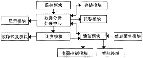
[0032] combined with figure 1 As shown, a power grid dispatching control system includes a data analysis and processing center and a display module, an alarm module, a communication module, a monitoring module and a dispatching module that are communicatively connected to the data analysis and processing center, and the communication module and the dispatching module connected, the communication module is also connected with an information collection module, and the information collection module includes a current transformer, a voltage transformer, and a collection terminal for collecting transformer output power and user-side power consumption information, and the communication module Also communicated with an intelligent terminal for controlling the on / off of household appliances and a power control module for controlling the on / off of the backup power supply, the power control module includes a relay controller communicatively connected with the communication module, and th...

Embodiment 2

[0036] On the basis of Example 1, in conjunction with the attached figure 1 As shown, the monitoring module is connected to the data analysis and processing center through a data bus, and the monitoring module includes a real-time load calculation unit, a power load forecasting unit, and an electric quantity for collecting voltage, current, frequency and active power of the power line Quality testing device.

[0037] working principle:

[0038] The real-time load calculation unit can read from the power metering automation system (TMR) in the power grid, or use the real-time monitoring system SCADA to detect the power load in the power grid to collect real-time load data, or collect the current of the power generation system equipment in the power grid and voltage, and use the power load integral calculation method to calculate the real-time total charge on the power line. The power load forecasting unit predicts the short-term power load by using a preset algorithm accordin...

Embodiment 3

[0040] On the basis of embodiment 2, in conjunction with the attached figure 1 As shown, the real-time load calculation unit includes a real-time load data acquisition circuit, and the real-time data acquisition circuit includes a voltage sampling circuit, a current sampling circuit and a signal conditioning circuit, and the voltage sampling circuit and the current sampling circuit input the collected data into the In the signal conditioning circuit, the output end of the signal conditioning circuit is connected to an analog-to-digital converter, and the analog-to-digital converter is connected to a single-chip microcomputer for calculating the electric load integral, and the single-chip microcomputer sends the result of the electric load integral calculation to the electric load forecasting unit.

[0041] working principle:

[0042] When the power load integral calculation method is used to calculate the real-time load on the power line, the current sampling circuit and the v...


PUM


Abstract

The invention discloses a grid scheduling control system comprising a data analysis and processing center, a communication module, a monitoring module and a scheduling module. The communication module is communicatively connected with an information acquisition module. The information acquisition module includes a current transformer, a voltage transformer and an acquisition terminal. The communication module is also communicatively connected with a power control module and a smart terminal. The power control module comprises a relay controller communicatively connected with the communication module. The relay controller is connected with a relay connected in series with a standby power supply. The grid scheduling control system utilizes the controllable load amount of a user to shut down the low-priority household appliances of the user by using the smart terminal to reduce the total load amount of the user, thereby reducing the maximum power load of the power grid at the peak hours of power consumption, reducing the cost of equipment such as transformers and power lines in the construction of the power grid and the replacement and maintenance cost of the transformers, and improving energy efficiency.

Description

technical field [0001] The invention relates to the field of power grid control systems, in particular to a power grid dispatching control system. Background technique [0002] In reality, the use of household appliances is increasing, and the demand for electric energy is also increasing, especially during the peak period of electricity consumption. Balanced to ensure the power demand during peak hours, often use the highest power load to set up the power grid. However, the problem that exists in this way is that the power grid is erected according to the highest power load, and the requirements for transformers, transmission lines, control and detection equipment of each node are very high, the total cost of construction is high, and the cost of transformer replacement and maintenance is also high very high. In non-peak hours, some power generation capacity is idle, and the energy utilization rate is not high. In recent years, with the aggravation of problems such as en...

Claims


Application Information

Patent Timeline
IPC IPC(8): H02J13/00H02J9/06
CPCH02J9/061H02J9/068H02J13/00H02J13/00001Y02B70/30Y02B90/20Y04S20/12Y04S20/20Y04S20/242Y04S20/248
Inventor 杨利华
Owner 成都源来来科技有限公司
Why Eureka
Try Eureka