Urea solution supply system

A solution supply and urea technology, applied in exhaust gas treatment, machine/engine, mechanical equipment, etc., can solve the problems of necessary compressed air source, poor resistance to impurities, easy urea crystallization, etc., to improve efficiency and reduce pump failure. , the effect of reducing energy consumption

Active Publication Date: 2017-12-15
HUST WUXI RES INST +1
View PDF5 Cites 4 Cited by
  • Summary
  • Abstract
  • Description
  • Claims
  • Application Information

AI Technical Summary

Problems solved by technology

[0004] The purpose of the present invention is to provide a urea solution supply system to solve the problems of urea easy to crystallize, serious blockage, poor resistance to impurities, and necessary compressed gas source in the urea solution supply system in the prior art

Method used


Image

  • Urea solution supply system
  • Urea solution supply system

Examples


Embodiment 1

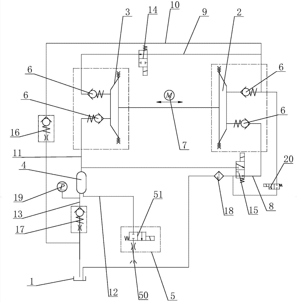
[0021] see figure 1 as shown, figure 1 It is a schematic structural diagram of the urea solution supply system provided in Embodiment 1 of the present invention.

[0022] In this embodiment, a urea solution supply system includes a urea tank 1, a first diaphragm pump 2, a second diaphragm pump 3, an accumulator 4 and a nozzle module 5 connected by pipelines, the first diaphragm pump 2 and A distribution valve 6 is installed on the pipelines of the liquid inlet end and the liquid outlet end of the second diaphragm pump 3, so that the diaphragm pump can only pump the solution in one direction to prevent backflow. Moreover, the first diaphragm pump 2 and the second diaphragm pump 3 are driven by the same motor 7, which can fully and effectively utilize the output torque of the motor, improve the efficiency of the entire diaphragm pump, reduce energy consumption, and reduce costs. There is a 180° phase difference between the first diaphragm pump 2 and the second diaphragm pump 3...

Embodiment 2

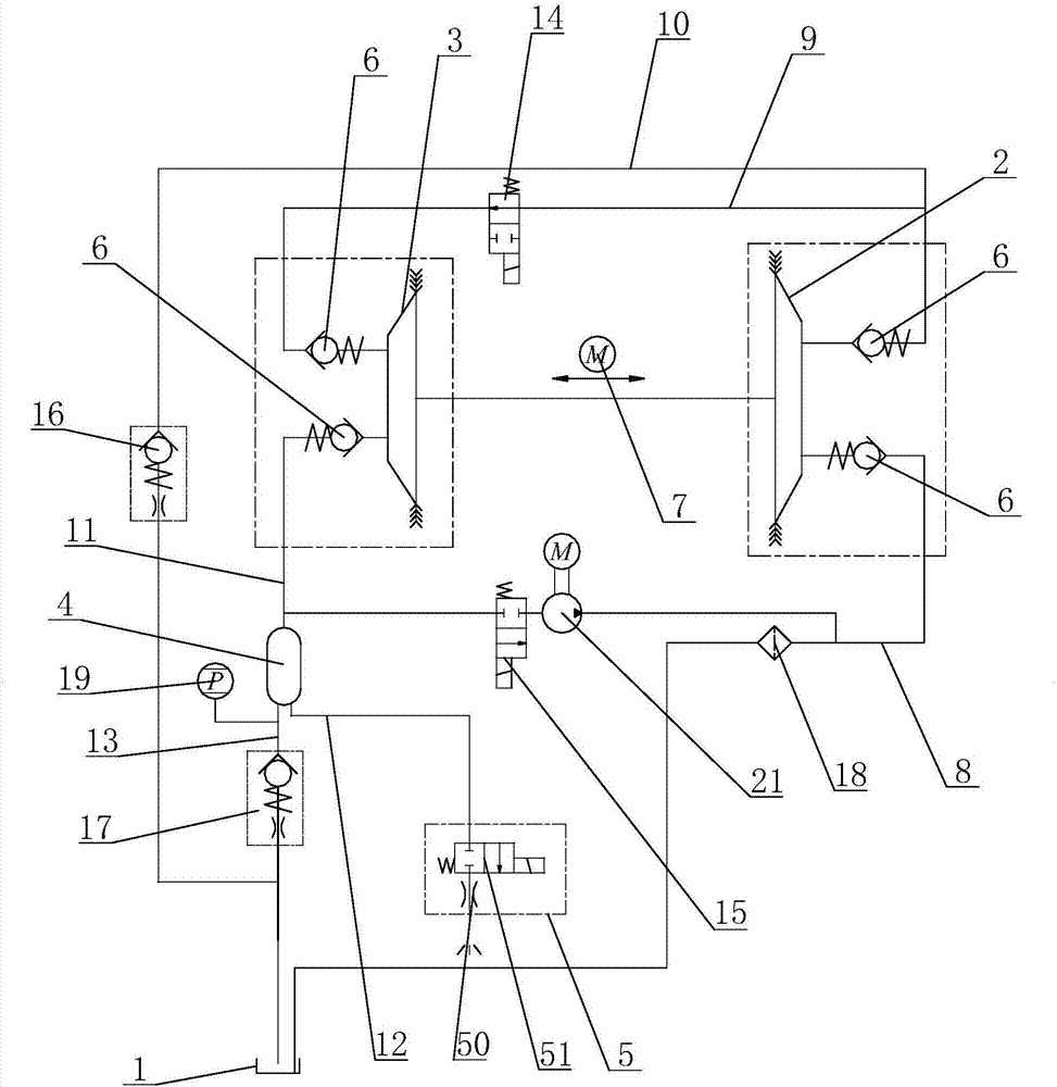
[0032] see figure 2 as shown, figure 2 It is a schematic structural diagram of the urea solution supply system provided in Embodiment 2 of the present invention.

[0033] The main difference between this embodiment and Embodiment 1 is that: a reverse suction pump 21 is installed on the pipeline between the liquid inlet pipeline 8 and the first liquid outlet pipe 11, and the second reversing valve 15 adopts a two-position two-position valve. The electromagnetic valve is connected, and the setting of the third reversing valve 20 is omitted at the same time, and the back pumping process is realized by the back pump 21, and the back pump 21 adopts any one of motor drive or electromagnetic drive. All the other parts are identical to the structure of Embodiment 1.


PUM


Abstract

The invention discloses a urea solution supply system. The urea solution supply system comprises a urea box, a first diaphragm pump, a second diaphragm pump, an energy storage device and a nozzle module which are connected through pipelines, wherein the first diaphragm pump communicates with the urea box through a liquid inlet pipeline; the liquid outlet end of the liquid inlet pipeline is divided into two pipelines, one pipeline is connected with the liquid inlet end of the second diaphragm pump through a connecting pipeline, and the other pipeline communicates with the urea box through a backflow pipeline; the second diaphragm pump is connected with the liquid inlet end of the energy storage device through a first liquid outlet pipeline, the liquid outlet end of the energy storage device is divided into two pipelines, one pipeline is connected with the nozzle module, and the other pipeline communicates with the urea box through a third liquid outlet pipeline; and a reversing valve is mounted on the connecting pipeline, a primary backflow module is mounted on the backflow pipeline, and a second backflow module is mounted on the third liquid outlet pipeline. The urea solution supply system not only can prevent urea from crystallizing and blocking the pipelines, but also is stable in running and low in noise and improves jet precision.

Description

technical field [0001] The invention belongs to the diesel engine tail gas post-treatment technology, in particular to an airless auxiliary urea solution supply system. Background technique [0002] In-machine purification technology cannot fully meet the increasingly stringent emission standards, so it is necessary to install exhaust after-treatment devices on diesel engines. The current mainstream post-treatment technology is SCR technology, which uses urea solution as a reducing agent to purify nitrogen oxides in exhaust gas. The urea solution supply system mainly includes: a urea tank for storing urea solution, a urea pump for pumping the urea solution in the urea tank into the exhaust pipe, a urea level sensor for detecting the liquid level in the urea tank, and preventing urea crystallization cooling water system. [0003] Currently, the air-assisted urea solution supply system is widely used in the market, in which a compressed air source is added, and the compresse...

Claims


Application Information

Patent Timeline
Patent Type & Authority Applications(China)
IPC IPC(8): F01N3/20
CPCF01N3/2066F01N2610/02F01N2610/14F01N2610/1473
Inventor 杨曙东史有程刘银水牛壮牛国贤潘希伟杜广杰
Owner HUST WUXI RES INST
Why Eureka
Try Eureka