Polycrystalline silicon reduction tail gas waste heat utilization method and system

A technology of polysilicon and exhaust gas, applied in chemical instruments and methods, waste heat treatment, silicon compounds, etc., can solve the problems of increased production cost, increased production cost, increased cooling load, etc., to increase reaction temperature, increase conversion rate and, The effect of reducing the cooling load

Active Publication Date: 2017-12-26
XINTE ENERGY
View PDF9 Cites 2 Cited by
  • Summary
  • Abstract
  • Description
  • Claims
  • Application Information

AI Technical Summary

Problems solved by technology

[0007] However, the inventors have found that in the existing method, although a suitable process control can be found through long-term process exploration, the primary conversion rate of TCS and the unit power consumption of polysilicon production can reach a better level, wherein the primary conversion rate of TCS can reach 9.4 %-9.8%, the unit power consumption can reach 60-62kwh / TSi, but in the process of pursuing these indicators, due to the high temperature of the silicon rod surface, the polysilicon surface of the silicon rod in the furnace near the crossbeam changes, resulting in this The surface of the silicon rod is uneven and may contain some impurities, which is difficult to meet the customer's requirements for the appearance and purity of the silicon rod
Therefore, although the existing method can reduce the unit consumption of electricity and improve the primary conversion rate of TCS, the resulting problems of appearance and purity of silicon rods will lead to low prices when the products are sold, thereby indirectly increasing production. cost
[0008] In addition, energizing the silicon rods to increase the surface temperature of the silicon rods, thereby increasing the reaction temperature in the furnace, will also cause the temperature of the reduction tail gas output from the reduction furnace to be too high (500-550 ° C), and the reduction tail gas will be exhausted even if it passes through the existing However, due to the high temperature of the reduction tail gas and the limited heat transfer area, the temperature of the reduction tail gas after heat exchange is still very high (220-240 ° C), which leads to an increase in the cooling load of the downstream process, and then lead to an increase in production costs

Method used


Image

  • Polycrystalline silicon reduction tail gas waste heat utilization method and system
  • Polycrystalline silicon reduction tail gas waste heat utilization method and system
  • Polycrystalline silicon reduction tail gas waste heat utilization method and system

Examples


Embodiment 1

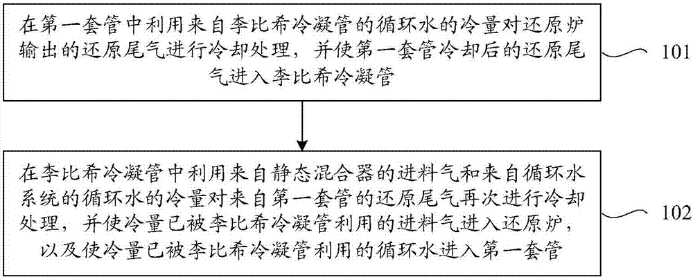
[0038] Such as figure 1 As shown, this embodiment provides a method for utilizing waste heat from polysilicon reduction tail gas, including the following steps S101 and S102.

[0039] S101. In the first sleeve, the cooling capacity of the circulating water from the Liebig condenser tube is used to cool the reduction tail gas output from the reduction furnace, and the reduced tail gas cooled by the first sleeve tube enters the Liebig condenser tube.

[0040] In this step, the reduction tail gas output from the reduction furnace includes a mixture of hydrogen, hydrogen chloride and chlorosilane, wherein the chlorosilane includes a mixture of trichlorosilane, silicon tetrachloride and dichlorodihydrosilane.

[0041] S102. In the Liebig condensing tube, use the cooling capacity of the feed gas from the static mixer and the circulating water from the circulating water system to cool the reduction tail gas from the first sleeve again, and make the cooling capacity have been obtained...

Embodiment 2

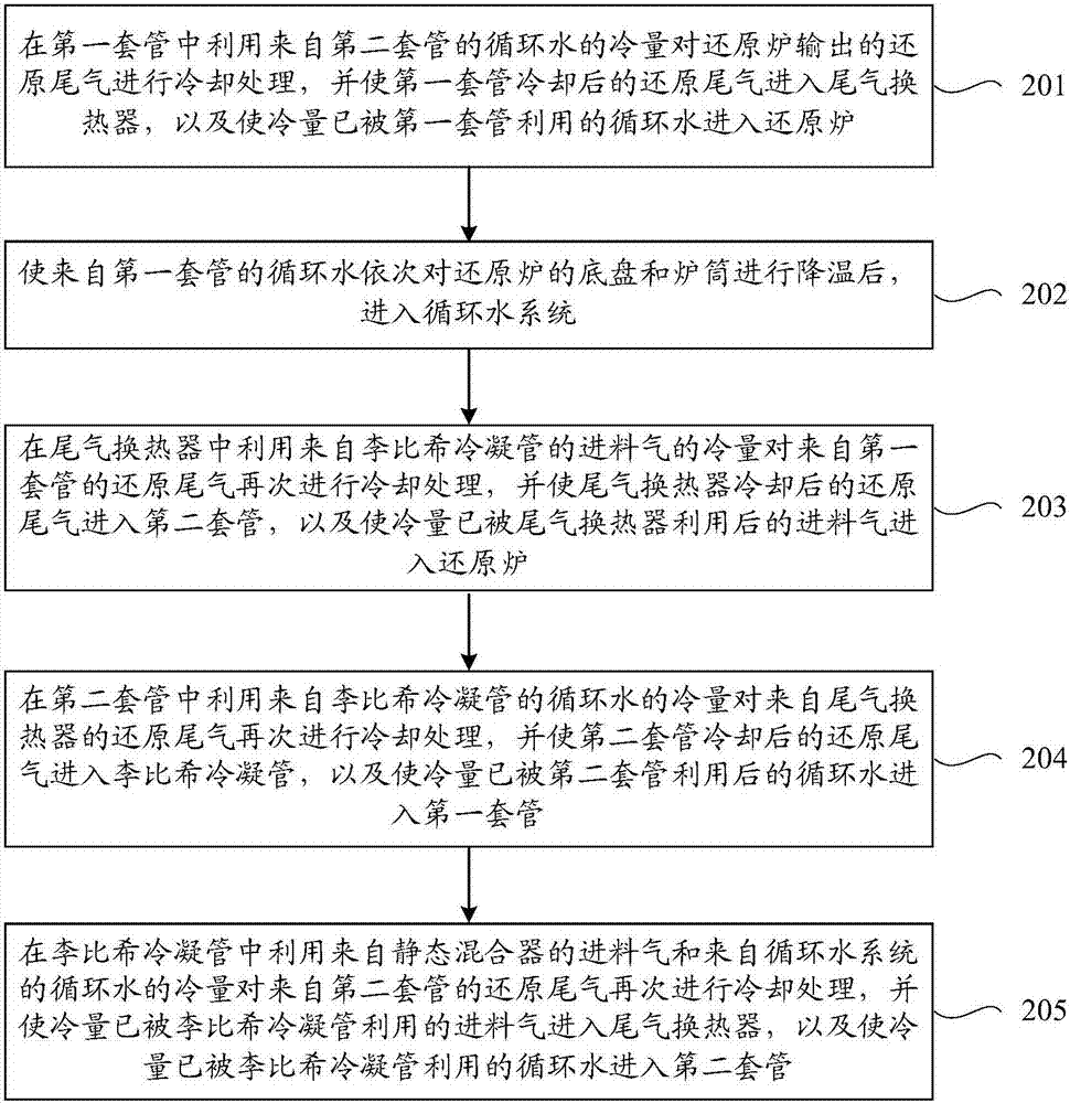
[0047] Such as figure 2 As shown, this embodiment takes the production process of polysilicon produced by 12 pairs of rod reduction furnaces as an example, and provides a method for utilizing waste heat of polysilicon reduction tail gas, including the following steps S201 and S205.

[0048] S201. In the first casing, the cooling capacity of the circulating water from the second casing is used to cool the reduction tail gas output from the reduction furnace, and the reduced tail gas cooled by the first casing enters the tail gas heat exchanger, and the The circulating water whose cooling capacity has been utilized by the first casing enters the reduction furnace.

[0049] S202. Make the circulating water from the first casing successively cool down the chassis and cylinder of the reduction furnace, and then enter the circulating water system.

[0050] S203. In the tail gas heat exchanger, the cooling capacity of the feed gas from the Liebig condenser tube is used to cool the ...

Embodiment 3

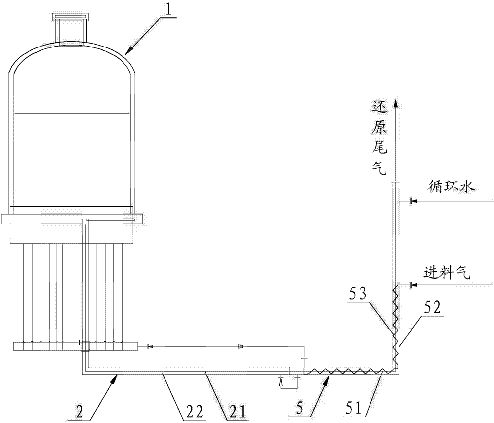
[0068] Such as image 3 As shown, this embodiment provides a polysilicon reduction tail gas waste heat utilization system, including a first sleeve 2 and a Liebig condenser tube 5 .

[0069] The first casing 2 is used to cool the reduction tail gas output from the reduction furnace by utilizing the cooling capacity of the circulating water from the Liebig condenser pipe 5 , and output the cooled reduction tail gas to the Liebig condenser pipe 5 .

[0070] Such as image 3 As shown, the first sleeve 2 includes an inner tube 21 and an outer tube 22 , and the outer tube 22 is sheathed outside the inner tube 21 . Wherein, the reduced tail gas flows through the inner pipe 21 , and the circulating water flows through the outer pipe 22 . The reduction tail gas output from the reduction furnace includes a mixture of hydrogen, hydrogen chloride and chlorosilane, wherein the chlorosilane includes a mixture of trichlorosilane, silicon tetrachloride and dichlorodihydrosilane.

[0071] ...


PUM


Abstract

The invention provides a polycrystalline silicon reduction tail gas waste heat utilization method. The method comprises the steps of: performing cooling treatment on reduction tail gas output from a reduction furnace with cooling capacity of circulating water from a Liebig condensation pipe in a first casing pipe, and letting the cooled reduction tail gas of the first casing pipe enter the Liebig condensation pipe; in the Liebig condensation pipe, utilizing the feed gas from a static mixer and the cooling capacity of circulating water from a circulating water system to perform cooling treatment again on the reduction tail gas from the first casing pipe, also making the feed gas with cooling capacity utilized by the Liebig condensation pipe enter the reduction furnace, and letting the circulating water with cooling capacity utilized by the Liebig condensation pipe enter the first casing pipe. Accordingly, the invention also provides a polycrystalline silicon reduction tail gas waste heat utilization system. The method and system provided by the invention can reduce the unit electricity consumption of polycrystalline silicon production and improve the primary conversion rate of TCS (trichlorosilane), also avoids the appearance problems of products, and effectively lowers the temperature of reduction tail gas.

Description

technical field [0001] The invention relates to the technical field of polysilicon production, in particular to a polysilicon reduction tail gas waste heat utilization method and a polysilicon reduction tail gas waste heat utilization system. Background technique [0002] Polysilicon is the building block material for the solar photovoltaic industry. At present, the production of polysilicon mainly adopts the improved Siemens method (that is, the reduction method of trichlorosilane), and the basic principle is to use SiHCl 3 (Trichlorosilane: trichlorosilane, referred to as TCS) and H 2 The vapor deposition reaction is carried out in a reduction furnace according to a certain ratio, and the reaction temperature is 1080°C to 1100°C, and the polysilicon crystal particles produced are deposited and grown on the silicon core to obtain rod-shaped polysilicon. [0003] The specific reaction equation is: [0004] 3SiHCl 3 +H 2 →2Si+5HCl+SiCl 4 [0005] In the process of prod...

Claims


Application Information

Patent Timeline
IPC IPC(8): C01B33/035F27D17/00
CPCC01B33/035F27D17/004Y02P10/25Y02P20/129
Inventor 桑友雷刘丹丹孙运德刘彬孙希德
Owner XINTE ENERGY
Why Eureka
Try Eureka