
Pre-amplifier circuit for photoelectric detector

A preamplifier circuit and photodetector technology, which is applied to light-controlled amplifiers, amplifiers with only semiconductor devices, diode amplifiers, etc., can solve the problem of low receiving sensitivity and response time requirements, high echo power, and large volume. and other problems, to achieve the effect of reducing the area of ​​the PCB layout, low switching frequency and small size

Inactive Publication Date: 2017-12-29
NANJING UNIV OF SCI & TECH
View PDF3 Cites 2 Cited by
  • Summary
  • Abstract
  • Description
  • Claims
  • Application Information

AI Technical Summary

Problems solved by technology

PIN photodiodes are generally used in occasions where there are strict requirements on the size of the receiving module, the echo power is large, and the requirements for photoelectric receiving sensitivity and response time are not high. Therefore, the traditional operational amplifier circuit uses an operational amplifier, which is larger and more costly.

Method used


Image

  • Pre-amplifier circuit for photoelectric detector
  • Pre-amplifier circuit for photoelectric detector
  • Pre-amplifier circuit for photoelectric detector

Examples


Embodiment Construction

[0018] It is easy to understand that, according to the technical solution of the present invention, those skilled in the art can imagine various implementations of the preamplifier circuit of the photodetector of the present invention without changing the essence of the present invention. Therefore, the following specific embodiments and drawings are only exemplary descriptions of the technical solution of the present invention, and should not be regarded as the entirety of the present invention or as a limitation or limitation on the technical solution of the present invention.

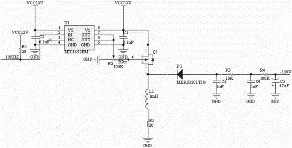
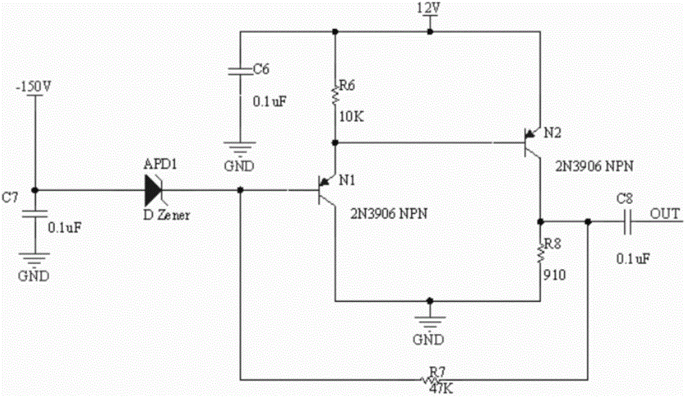
[0019] The pre-amplification circuit of the photodetector of the present invention includes a high-voltage generating circuit and a pre-amplifying circuit, and the negative high-voltage generating circuit provides high voltage for the pre-amplifying circuit to drive the avalanche photodiode APD to work.

[0020] combine figure 1 , The negative high voltage generating circuit includes a MOS tube drive...


PUM


Abstract

The invention provides a pre-amplifier circuit for a photoelectric detector, comprising a high voltage generation circuit and a pre-amplifier, wherein a negative high voltage generation circuit supplies high voltage to the pre-amplifier, thereby driving an avalanche photodiode to work. An MOS transistor drive chip generates a switching signal based on an access 10KHZ square wave, thereby controlling on-off of a switch MOS transistor chip; a first inductor is charged by a power supply voltage at the moment when the switch MOS transistor chip is switched on; the power is stored in a third capacitor, a forth capacitor and a fifth capacitor through a first diode circuit; after the switch MOS transistor chip is switched off, a first diode is reversely cut off, so an output capacitor discharges power to a load; and a third resistor, a fourth resistor, the third capacitor and the fourth capacitor form a second-order RC filter circuit. The pre-amplifier is small in size and stable in performance.

Description

technical field [0001] The invention belongs to the technical field of sensor receiving circuits, and in particular relates to a preamplifying circuit of a photodetector. Background technique [0002] In the receiving circuit of the sensor, the photodetector can measure the light signal, and it is widely used in laser ranging, medicine, navigation and so on. Generally, the signal received by the sensor is very weak. In order to amplify the weak signal to a level that can be detected, a preamplifier circuit is required. Usually, the improper use of passive components is likely to cause the instability of the entire amplifying circuit, the noise is large and the detected signals are superimposed, and accurate measurement data cannot be obtained. [0003] The photodetection devices commonly used in traditional preamplification circuits include photomultiplier tubes, PIN photodiodes, and avalanche photodiodes. Among them, the photomultiplier tube has the disadvantages of large...

Claims


Application Information

Patent Timeline
Patent Type & Authority Applications(China)
IPC IPC(8): H03F1/26H03F1/34H03F3/08H03F3/10
CPCH03F1/26H03F1/34H03F3/08H03F3/10
Inventor 钱惟贤李之秀顾国华陈钱杨锦清钱烨高青松
Owner NANJING UNIV OF SCI & TECH
Learn More