

Method for removing welding residual stresses
A residual stress and weldment technology, applied in the improvement of process efficiency, furnace type, furnace and other directions, can solve the problems of stress corrosion cracking and high temperature fatigue of weldments, and achieve the elimination of temperature thermal stress, increase speed life, eliminate controllable The effect of susceptibility and optimizability
- Summary
- Abstract
- Description
- Claims
- Application Information
AI Technical Summary
Problems solved by technology
Method used
Image

Examples
Embodiment 1
[0060] Example 1: Welding of plates to plates
[0061] image 3 Depicted is a square waste container containing a corrosive liquid; two perpendicular plates welded together. In order to effectively prevent stress corrosion cracking, the residual tensile stress inside the container must be eliminated.
[0062] When welding, deliberately make the angle between the two plates 91 degrees. After soldering is completed, the Figure 4 As shown in the plastic bending mold (forming mold 1, bending mold 2, welding plate 3), while the welded part is subjected to in-plane compressive stress (inplane), the weldment at an angle of 91 degrees produces 1% linear deformation and 1% The angular deformation is extruded to 90 degrees, resulting in plastic angular deformation. Using the plastic deformation finite element calculation, considering the spring back plastic bending deformation, the angle between the two plates is 90 degrees, so that the stress between the welds is compressive stres...
Embodiment 2
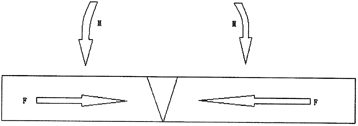
[0063] Example 2: Rotor and rotor welding
[0064] see Figure 5 and Figure 6 As shown, the second case describes a gas turbine rotor-to-rotor weld structure. There is relatively high-temperature gas (>650°C) on the outside of the rotor, and cooling gas passes through it from the inside. In order to effectively improve the life of thermal mechanical fatigue, the residual tensile stress on the outside of the tube must be eliminated. The loading mode of mechanical plastic deformation of weld seam is as follows: Figure 6 As shown, in the process of structural design, a ring-shaped process structure is reserved on both sides of the weld, and the ring structure is axially pressed by a hydraulic device. The pressure in the axial direction will generate a bending moment on the weld. This pressure and bending moment can eliminate the residual tensile stress on the outside of the rotor. After the method of eliminating residual stress is implemented, the reserved ring structure ca...
Embodiment 3
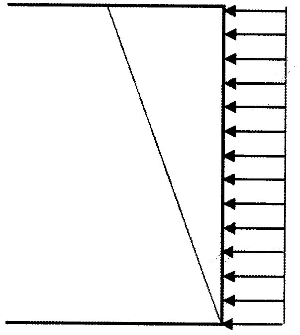
[0066] Example 3: Welding of pipes and pipes
[0067] see Figure 7 As shown, the third case is the welding of pipes and pipes. This pipe is used to transport corrosive liquids and eliminate the residual tensile stress measured inside the pipe, which can effectively prevent stress corrosion cracking. The mechanical plastic deformation loading mode of the weld is plastic displacement deformation in the radial direction of the pipeline. Through the hydraulic device, the pressure F1 is applied radially on both sides of the pipe weld to produce a radial displacement in the range of 0.5% to about 1.0%, which offsets the temperature residual stress of the pipe and generates a certain compressive stress inside the pipe. This mitigates and prevents the potential for corrosion cracking to occur.
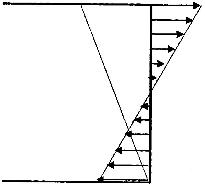
[0068] If the welded pipe is short, the compressive external force F2 can also be applied directly axially along both ends of the welded pipe.
PUM
 Abstract
Description
Claims
Application Information