Broadband slot antenna unit and slot antenna

A technology for slot antennas and antenna units, which is applied in slot antennas, antenna unit combinations with different polarization directions, antennas, etc., can solve the problems of limited vertical angle, insufficient gain strength, and high production costs, and achieve linear polarization, The effect of extending the feed transmission distance and making it easy to produce

Pending Publication Date: 2018-01-12
深圳市普方众智精工科技有限公司
View PDF0 Cites 11 Cited by
  • Summary
  • Abstract
  • Description
  • Claims
  • Application Information

AI Technical Summary

Problems solved by technology

Among these requirements, the cross-shaped half-wave dipole or rhombus unit is the preferred solution for most designs, because the half-wave dipole unit has good broadband characteristics, compact structure, and is convenient for dual-polarization design. Feed balun It is convenient to fix the structure. This type of array is processed by die-casting or sheet metal stamping. The surface is treated with electroplating copper and tin plating, which is convenient for feeding and grounding welding. The array is connected with the reflector by fasteners, but its production cost is relatively high. , complex structure and insufficient antenna frequency bandwidth and gain strength, and the vertical plane angle is limited

Method used


Image

  • Broadband slot antenna unit and slot antenna
  • Broadband slot antenna unit and slot antenna
  • Broadband slot antenna unit and slot antenna

Examples


Embodiment 1

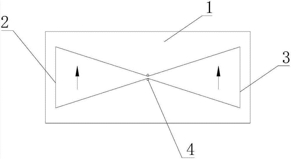
[0038] This embodiment provides a broadband slot antenna unit, such as figure 1 As shown, it is a planar patch structure, including a patch layer 1, and the patch layer 1 is an aluminum plate. In this embodiment, the model of the aluminum plate is 5052-H32, and the shape of the patch layer 1 can be rectangular Or an axisymmetric hexagon. In this embodiment, it is a rectangle as shown in the figure. A first radiating slot 2 and a second radiating slot 3 are arranged symmetrically along the midline of the long side and short side of the rectangle. The first radiating slot 3 The slit 2 and the second radiating slit 3 can be axisymmetric triangles or other polygons. In this embodiment, they are isosceles triangles with a simple structure, and the apex angles of the two isosceles triangles are relatively arranged, and the angle of the apex angles is 30- 40°, in order to realize the broadband impedance characteristic, along the direction of the height of the isosceles triangle, form...

Embodiment 2

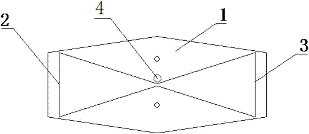
[0040] This embodiment provides a broadband slot antenna unit, which includes a patch layer 1, such as figure 2 As shown, in this embodiment, the shape of the patch layer 1 is an axisymmetric hexagon. As shown in the figure, the symmetry axes of the hexagon are respectively the horizontal symmetry axis and the vertical symmetry axis. A first radiation slot 2 and a second radiation slot 3 are symmetrically arranged on the sheet 1 along two symmetrical axes, and the first radiation slot 2 and the third radiation slot 3 are both isosceles triangles, and the tops of the two isosceles triangles The corners are oppositely arranged, and the angle of the top corners is 30-40°. The top corners of the first slot 2 and the second slot 3 are also crimped with copper rivet feeder terminals 4 .

Embodiment 3

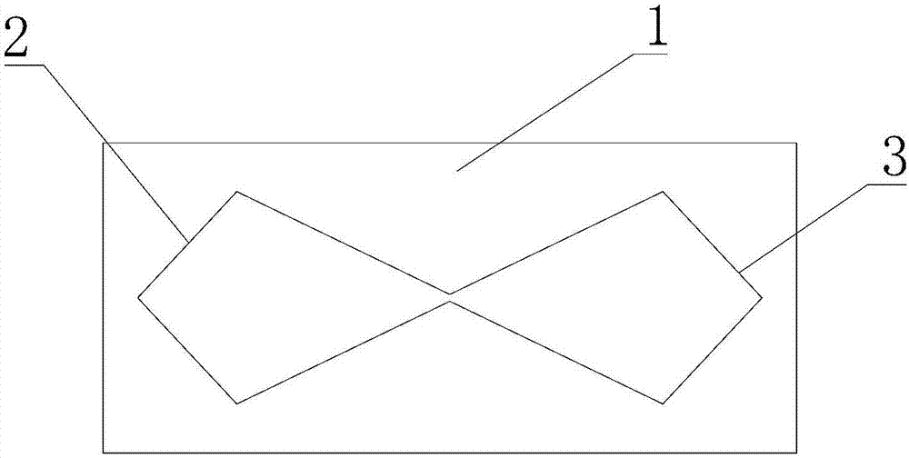
[0042] This embodiment provides a broadband slot antenna unit, such as image 3 As shown, its structure is basically the same as the antenna unit described in Embodiment 1, the difference is that the shapes of the first radiation slot 2 and the second radiation slot 3 are different, as shown in the figure, in this embodiment, the first radiation slot 2 The shapes of the first radiating slot 2 and the second radiating slot 3 are axisymmetric quadrilaterals with two groups of adjacent sides of equal length respectively. Connected arrangement, the two opposite angles are 30-40°, and copper rivet feed ends (not shown in the figure) are provided at the two opposite corners.


PUM


Abstract

The invention discloses a broadband slot antenna unit, which comprises a patch layer, wherein a first radiation slot and a second radiation slot are formed in the patch layer, the shapes of the firstradiation slot and the second radiation slot are polygonal, and the first radiation slot and the second radiation slot are connected with a feed terminal. The antenna unit adopts a planar patch structure, has the advantages of simple structure, easy production and manufacturing, low cost, long feed transmission distance and excellent feature of ultra-wideband. The invention further provides a slotantenna, which comprises an antenna unit array formed by the broadband slot antenna units which are reasonably distributed, and the spacing between the antenna units determines the beamwidth of the antenna horizontal plane. The slot antenna has the advantages of high gain, good isolation effect and low cost, and can used as a community beautification spotlight antenna or other base station antenna.

Description

technical field [0001] The invention belongs to the technical field of antennas, and relates to a mobile communication system base station antenna, in particular to a broadband slot antenna unit and a slot antenna. Background technique [0002] The antenna is an indispensable component of any radio system. Its function is to radiate or receive radio waves. It converts guided electromagnetic waves into radio waves in free space (in the transmitting system), or vice versa (in the receiving system). Thereby realizing one-to-one or many-to-many wireless communication within a certain space range, which is widely used in radio systems such as communication, broadcasting, television, radar and navigation. [0003] In recent years, with the popularization of 3G communication technology and the rise of 4G communication technology, the existing spectrum resources are increasingly tight, and it is imminent to find antennas with wide spectrum and efficient spectrum utilization. UWB te...

Claims


Application Information

Patent Timeline
Patent Type & Authority Applications(China)
IPC IPC(8): H01Q1/24H01Q1/36H01Q1/50H01Q1/52H01Q13/10H01Q19/10H01Q21/24
Inventor 刘红波
Owner 深圳市普方众智精工科技有限公司
Why Eureka
Try Eureka