Chemical vapor deposition furnace

A chemical vapor deposition and deposition chamber technology, applied in gaseous chemical plating, metal material coating process, coating, etc., can solve problems affecting system pressure, entry, and production, and achieve high product conversion rate and thickness deviation Small, well-structured effects

Active Publication Date: 2018-01-19
安徽光智科技有限公司
View PDF17 Cites 6 Cited by
  • Summary
  • Abstract
  • Description
  • Claims
  • Application Information

AI Technical Summary

Problems solved by technology

Zinc sulfide production by chemical vapor deposition generally uses zinc and hydrogen sulfide as raw materials. Most of the zinc sulfide produced by the reaction of zinc and hydrogen sulfide will be deposited in the deposition chamber, but some will still enter the deposition chamber. If the chemical vapor deposition furnace Unreasonable design will affect the pressure of the system and affect the progress of production

Method used


Image

  • Chemical vapor deposition furnace
  • Chemical vapor deposition furnace

Examples


Embodiment 1

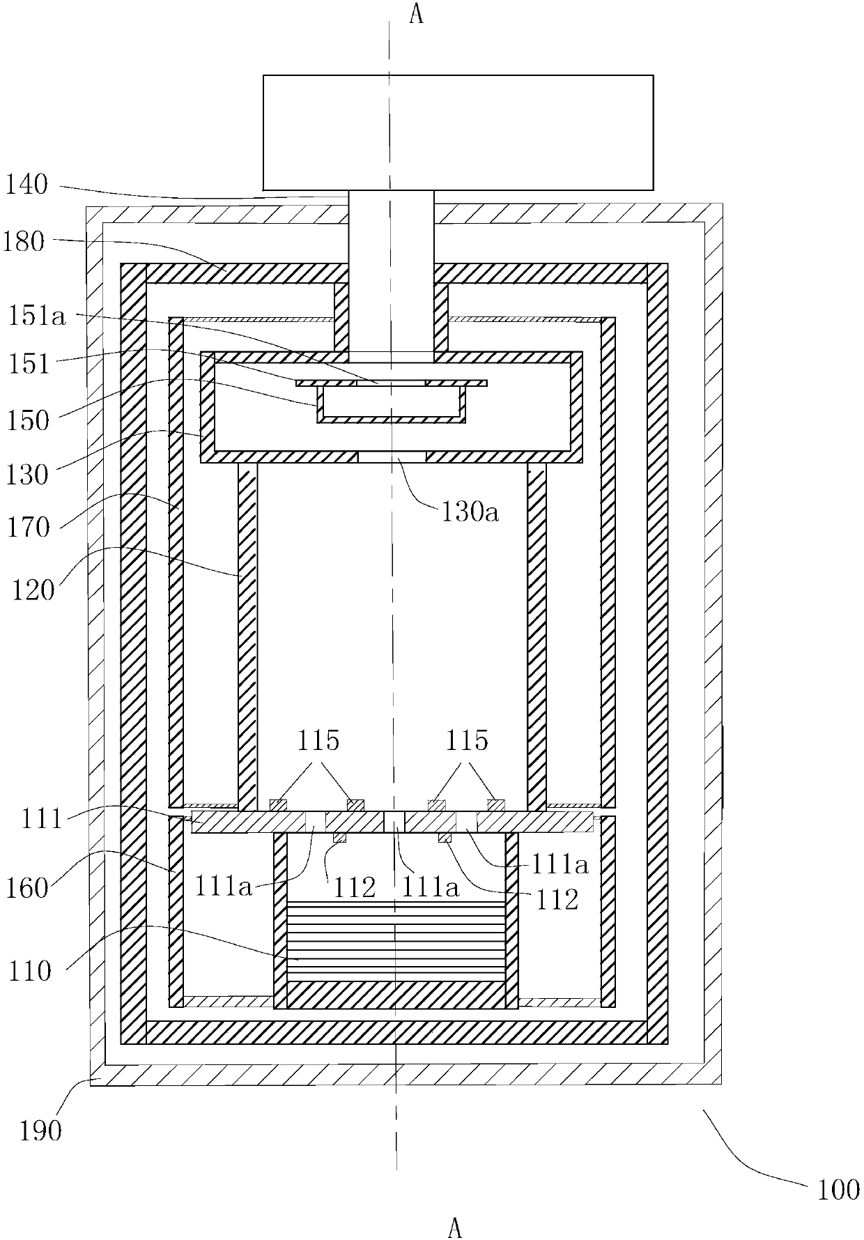
[0020] see figure 1 , the chemical vapor deposition furnace 100 of the present invention comprises a crucible 110 assembled from bottom to top for containing raw materials, a crucible cover 111 used in conjunction with the crucible 110, a deposition chamber 120, a material receiving box 130, a guide Gas pipe 140; the crucible cover 111 is provided with some first through holes 111a connecting the crucible 110 and the deposition chamber 120, and the receiving box 130 is provided with a second through hole 130a connecting the deposition chamber 120 and the receiving box 130, chemical vapor phase The deposition furnace 100 also includes a first heater 160 for heating the crucible 110, a dust collection chamber 150 and a dust collection chamber cover 151 built in the material receiving box 130 above the dust collection chamber 150, the dust collection chamber cover 151 defines a third through hole 151a that communicates with the dust collection chamber 150 and the material receivi...

Embodiment 2

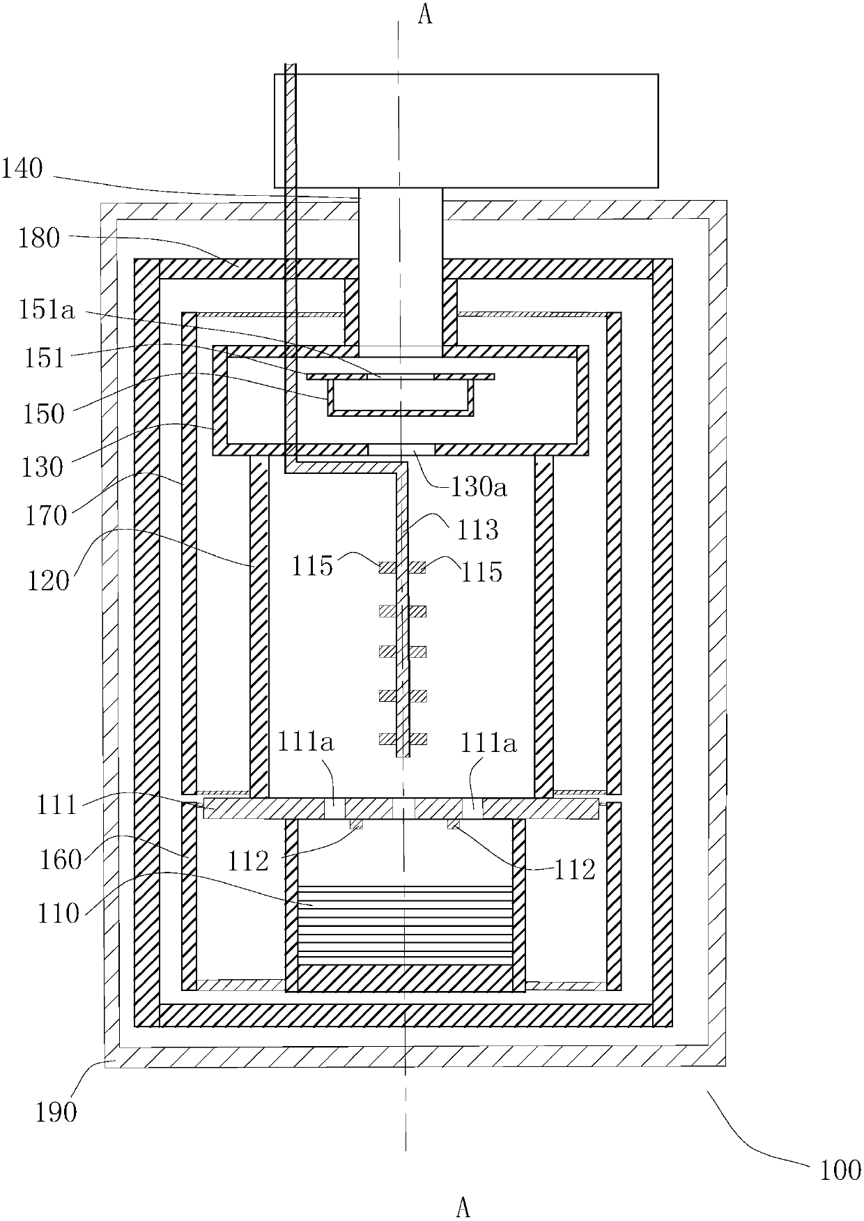
[0035] see figure 2Most of the structures of Embodiment 2 are the same as those of Embodiment 1, except that the second air inlet pipe 113 ventilates from the water-cooled jacket 190 to the deposition chamber 120, and the second air inlet pipe 113 is vertically inserted into the deposition chamber 120. The two inlet holes 115 are evenly and equidistantly distributed on both sides of the second inlet pipe 113. This design is more conducive to the hydrogen sulfide entering the deposition chamber 120 through the second inlet pipe 113 and the hydrogen sulfide entering the deposition chamber 120 through the first through hole 111a. The zinc vapor is fully mixed to make the chemical reaction more fully.

[0036] It is worth noting that the chemical vapor deposition furnace 100 can also be used to prepare other similar crystals or powders, such as zinc selenide, in addition to being used for preparing zinc sulfide crystals.

[0037] The chemical vapor deposition furnace 100 of the ...


PUM


Abstract

The invention relates to a chemical vapor deposition furnace. The chemical vapor deposition furnace comprises a crucible used for containing raw materials, a crucible cover used in cooperation with the crucible, a deposition chamber, a material collecting box and a gas guide tube, wherein the crucible, the crucible cover, the deposition chamber, the material collecting box and the gas guide tube are assembled from bottom to top; a plurality of first through holes making the crucible and the deposition chamber communicate are formed in the crucible cover, and a second through hole making the deposition chamber and the material collecting box communicate is formed in the material collecting box; and the chemical vapor deposition furnace further comprises a first heater used for heating the crucible, a dust collecting chamber and a dust collecting chamber cover plate covering the dust collecting chamber are arranged inside the material collecting box, and a third through hole making the dust collecting chamber and the material collecting box communicate is formed in the dust collecting chamber cover plate. The chemical vapor deposition furnace is reasonable in structure, multi-stage collection is carried out on zinc sulfide products, defects such as fog spots, fog layers and patterns do not exist in the prepared zinc sulfide, the overall thickness deviation of the zinc sulfide products is small, and the product conversion rate is high.

Description

technical field [0001] The invention relates to the field of powder or crystal preparation devices, in particular to a chemical vapor deposition furnace. Background technique [0002] Zinc sulfide is an infrared material, and its production method generally adopts chemical vapor deposition. The production equipment of zinc sulfide generally includes the following parts: electrical control system, gas supply system, cooling circulating water system, chemical vapor deposition furnace, dust collection system, vacuum system and tail gas treatment system. Among them, the electrical control system is mainly used for Various process parameters and equipment are controlled during the production process. The gas supply system is mainly used to supply the process gas required in the production process; the cooling circulating water system is mainly used to cool down the production equipment; the chemical vapor deposition furnace is the main equipment of the entire production device ,...

Claims


Application Information

Patent Timeline
Patent Type & Authority Applications(China)
IPC IPC(8): C23C16/30C23C16/448C23C16/455
CPCY02P70/50
Inventor 于金凤朱刘
Owner 安徽光智科技有限公司
Why Eureka
Try Eureka