Preparation method and application of membrane electrode based on platinum or platinum alloy nanotube

A membrane electrode, platinum alloy technology, applied in battery electrodes, circuits, fuel cells, etc., can solve the problems of disordered accumulation of catalysts, high consumption of precious metals, low utilization rate of catalysts, etc. The effect of thin thickness and mild preparation conditions

Active Publication Date: 2018-01-23
DALIAN INST OF CHEM PHYSICS CHINESE ACAD OF SCI
View PDF11 Cites 14 Cited by
  • Summary
  • Abstract
  • Description
  • Claims
  • Application Information

AI Technical Summary

Problems solved by technology

The traditional CCM electrode and GDE electrode have mature preparation technology, but the thickness of the catalytic layer of the electrode is large, and the catalyst is piled up disorderly, which makes the amount of catalyst used high and the utilization rate of catalyst low
In order to solve the problems of high consumption o

Method used


Image

  • Preparation method and application of membrane electrode based on platinum or platinum alloy nanotube
  • Preparation method and application of membrane electrode based on platinum or platinum alloy nanotube
  • Preparation method and application of membrane electrode based on platinum or platinum alloy nanotube

Examples


Embodiment 1

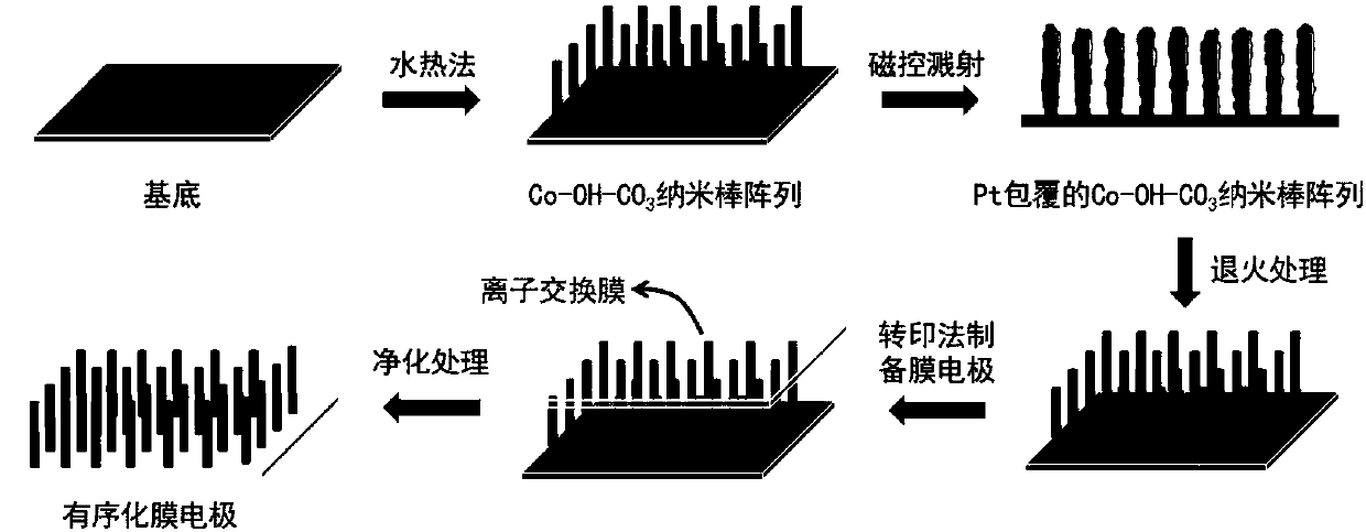
[0040] Preparation of Co-OH-CO by hydrothermal method using stainless steel as substrate 3 array. The reaction solution was 10 mM ammonium fluoride, 25 mM urea, and 5 mM cobalt nitrate. React in a high-pressure reactor at 120°C for 5 hours to prepare Co-OH-CO on the substrate 3 array. figure 2 Shown is the prepared Co-OH-CO 3 SEM image of the nanorod array. It can be seen from the figure that Co-OH-CO 3 The nanorod array grows uniformly on the substrate, and the growth direction is substantially perpendicular to the substrate. Co-OH-CO 3 The length of the nanorod is about 3μm, the diameter is about 100nm, Co-OH-CO 3 The areal density of nanorods is 3-4e 9 / cm 2 .

[0041] Co-OH-CO was deposited by magnetron sputtering 3Pt is loaded on the array. The magnetron sputtering power is 150W, the sputtering time is 10min, and the operating pressure is 1.0Pa. Co-OH-CO loaded with Pt 3 array at 300°C, H 2 -Ar(H 2 The volume fraction is 5%) and annealed for 60 min in an ...

Embodiment 2

[0047] Preparation of Co-OH-CO by hydrothermal method using stainless steel as substrate 3 array. The reaction solution was 10 mM ammonium fluoride, 25 mM urea, and 5 mM cobalt nitrate. React in a high-pressure reactor at 120°C for 4 hours to prepare Co-OH-CO on the substrate 3 array.

[0048] Co-OH-CO was deposited by magnetron sputtering 3 PtCo (atomic ratio 3:1) is supported on the array. The magnetron sputtering power is 100W, the sputtering time is 20min, and the operating pressure is 1.0Pa. Co-OH-CO loaded with PtCo 3 array at 400°C, H 2 -Ar(H 2 The volume fraction is 5%) and annealed for 1 h under the atmosphere. Figure 7 Shown is the SEM image of the as-prepared platinum-cobalt nanotube array. It can be seen from the figure that magnetron sputtering in Co-OH-CO 3 The uniform PtCo catalyst is loaded on the surface of the nanorod array, the thickness of the PtCo coating is about 18nm, and the annealing treatment does not destroy the order of the array. Co-OH-...

Embodiment 3

[0053] Co-OH-CO 3 Refer to Example 2 for the preparation method of the array.

[0054] Co-OH-CO was deposited by magnetron sputtering 3 PtFe (atomic ratio 1:1) is supported on the array. The magnetron sputtering power is 100W, the sputtering time is 20min, and the operating pressure is 1.0Pa. Co-OH-CO loaded with PtFe 3 array at 600°C, H 2 -Ar(H 2 The volume fraction is 5%) and annealed for 1 h under the atmosphere. Figure 11 Shown is the scanning electron microscope image of the prepared nanorod array. It can be seen from the figure that the prepared PtFe nanorods grow vertically on the substrate with a certain orientation, and the Co-OH-CO loaded with PtFe coating 3 The nanorods are about 2.5 μm in length and about 130 nm in diameter.

[0055] Refer to Example 2 for the preparation process of the membrane electrode. Figure 12 It is a scanning electron microscope picture of the prepared membrane electrode. It can be seen from the picture that the prepared catalytic ...


PUM

PropertyMeasurementUnit
Diameteraaaaaaaaaa
Lengthaaaaaaaaaa
Thicknessaaaaaaaaaa

Abstract

The invention discloses a preparation method and an application of a membrane electrode based on a platinum or platinum alloy nanotube. The preparation method comprises the steps of formation of an ordered electrode micro-structure, preparation of the platinum or platinum alloy nanotube, and assembling of the membrane electrode. A Co-OH-CO<3> nanorod array with regular orientation is grown on a substrate firstly; next, the array is loaded with a catalyst, and the Co-OH-CO<3> nanorod array loaded with the catalyst is subjected to annealing treatment; and finally, the array is thermally pressedon an ion exchange membrane to obtain the membrane electrode, and the membrane electrode is subjected to purification treatment, wherein the constructed membrane electrode can be applied to a fuel cell. The membrane electrode constructed in the invention has the advantages of low catalyst loading amount, high catalyst utilization rate, easy amplification and the like.

Description

technical field [0001] The invention relates to a method for preparing a membrane electrode, which belongs to the field of fuel cells. Background technique [0002] A fuel cell is a highly efficient energy conversion device that efficiently converts chemical energy stored in chemical substances into electrical energy. At present, fuel cells have been applied in many fields such as electric vehicles, distributed power stations, and aviation. Proton exchange membrane fuel cells have attracted widespread attention due to their advantages such as high power density, fast start-up speed, high conversion efficiency, and environmental friendliness. [0003] The membrane electrode assembly (MEA) is the core component of the electrochemical reaction of the fuel cell, which consists of a catalytic layer and a gas diffusion layer located on both sides of the proton exchange membrane. Membrane electrodes are mainly divided into gas diffusion electrodes (Gas Diffusion Electrode, GDE), ...

Claims


Application Information

Patent Timeline
IPC IPC(8): H01M4/88H01M4/86H01M4/92H01M8/1004
CPCY02E60/50
Inventor 邵志刚曾亚超俞红梅郭晓倩宋微张洪杰衣宝廉
Owner DALIAN INST OF CHEM PHYSICS CHINESE ACAD OF SCI
Why Eureka
Try Eureka