Automatic control system for humidity and temperature of working environment of non-airtight-sealing laser device
An automatic control system and working temperature technology, applied in the direction of control/regulation system, non-electric variable control, laser, etc., can solve the problems of reducing the reliability and life of laser, so as to increase the reliability of work, improve high-speed performance, expand Effect of Operating Temperature Range
- Summary
- Abstract
- Description
- Claims
- Application Information
AI Technical Summary
Problems solved by technology
Method used
Image
Examples
Embodiment 1
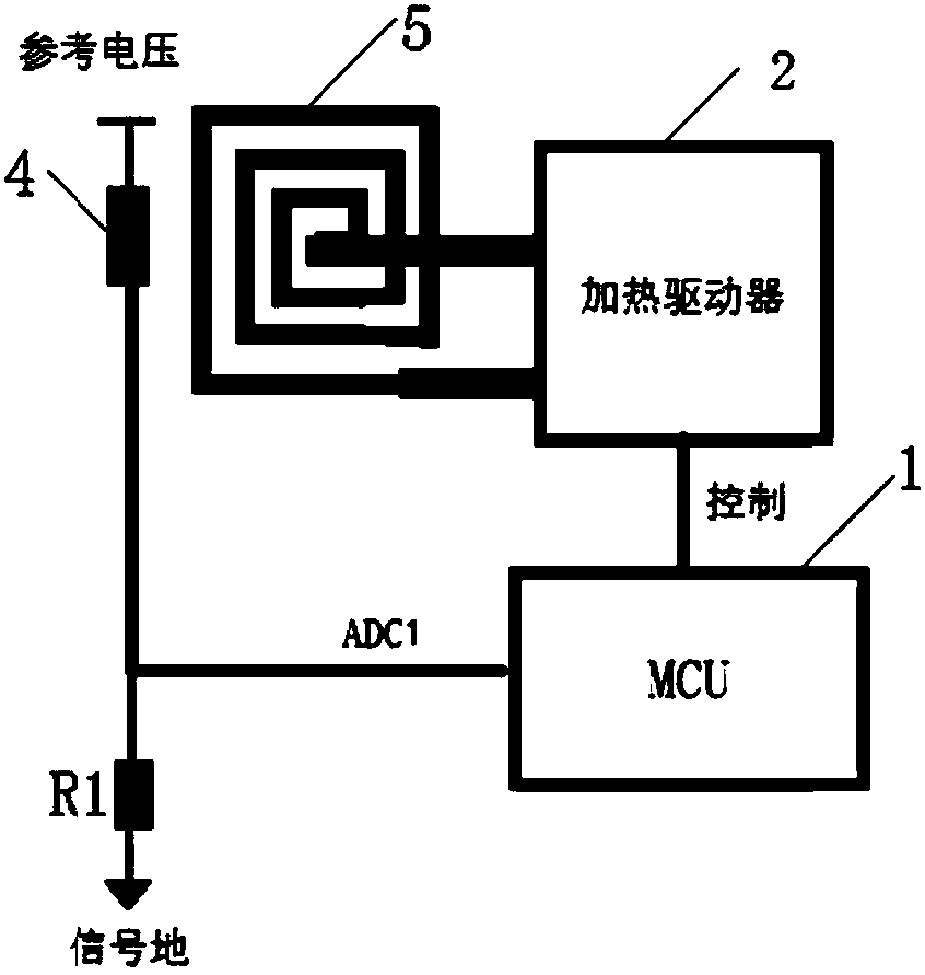
[0026] Such as figure 1 and figure 2 As shown, a non-hermetic packaging laser working environment temperature automatic control system of the present invention includes: a heating coil 5 embedded in the laser carrier PCB and located below the laser 3, and also includes: a thermistor 4, a sampling resistor R1 , the first analog-to-digital converter ADC1, the micro control unit 1, the coil heating driver 2; the thermistor 4 is placed next to the laser for sensing the operating temperature of the laser, the first end of the thermistor 4 is connected to a reference voltage, and the thermistor 4. The second end is connected to the first end of the sampling resistor, and the second end of the sampling resistor is grounded; the second end of the thermistor 4 is also connected to the micro-control unit 1 through the first analog-to-digital converter ADC1, and the micro-control unit 1 The heating coil 5 is controlled by the coil heating driver 2 to work.
[0027] The laser in this e...
Embodiment 2
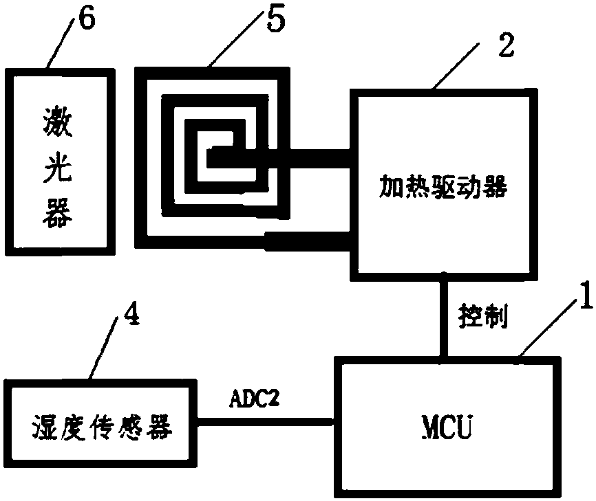
[0031] Such as image 3 As shown, a non-hermetic packaging laser working environment humidity automatic control system of the present invention includes: a heating coil 5 embedded in the laser carrier PCB and located below the laser 3, and also includes: a humidity sensor 7, a second modulus Converter ADC2, micro control unit 1, coil heating driver 2; humidity sensor 7 is placed next to the laser for sensing the working humidity of the laser, and humidity sensor 7 is connected to micro control unit 1 through the second analog-to-digital converter ADC2, and the micro control The unit 1 controls the heating coil 5 to work through the coil heating driver 2 .
[0032] The working principle is: the humidity sensor 7 is installed close to the laser 3, and the humidity sensor 7 senses the working humidity of the laser 3; the micro-control unit 1 obtains the current working humidity of the laser according to the signal sent by the second analog-to-digital converter ADC2, when When it...
Embodiment 3
[0035] Such as Figure 4 As shown, the non-hermetically sealed laser working environment temperature and humidity automatic control system includes: a heating coil 5 embedded in the laser carrier PCB and located under the laser 3, and also includes: a thermistor 4, a humidity sensor 7, and a sampling resistor R1, a first analog-to-digital converter ADC1, a second analog-to-digital converter ADC2, a micro control unit 1, and a coil heating driver 2;
[0036] The thermistor 4 is placed next to the laser for sensing the working temperature of the laser, the first end of the thermistor 4 is connected to the reference voltage, the second end of the thermistor 4 is connected to the first end of the sampling resistor R1, and the second end of the sampling resistor R1 is grounded ; The second end of the thermistor 4 is also connected to the micro control unit 1 through the first analog-to-digital converter ADC1, and the micro control unit 1 controls the heating coil 5 to work through ...
PUM
 Abstract
Description
Claims
Application Information
 - R&D
- Intellectual Property
- Life Sciences
- Materials
- Tech Scout
- Unparalleled Data Quality
- Higher Quality Content
- 60% Fewer Hallucinations
Browse by: Latest US Patents, China's latest patents, Technical Efficacy Thesaurus, Application Domain, Technology Topic, Popular Technical Reports.
© 2025 PatSnap. All rights reserved.Legal|Privacy policy|Modern Slavery Act Transparency Statement|Sitemap|About US| Contact US: help@patsnap.com


