Power and water joint supply device
A supply device, a technology of a supply device, applied in the direction of hot gas variable displacement engine device, gas turbine device, water, etc.
- Summary
- Abstract
- Description
- Claims
- Application Information
AI Technical Summary
Problems solved by technology
Method used
Image

Examples
Embodiment 1
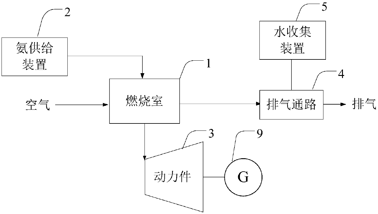
[0029] like figure 1 The shown combined power and water supply device includes a combustion chamber 1, an ammonia supply device 2, a power member 3 and a water collection device 5, the ammonia supply device 2 can be connected to the combustion chamber 1 to supply ammonia to the combustion chamber 1, the combustion chamber 1 also receives air supply, the combustion chamber 1 is connected to the power member 3 to push the power member 3 to move through the exhaust gas generated by the combustion of the combustion chamber 1, the combustion chamber 1 has an exhaust passage 4, and the water collection device 5 is provided in the exhaust passage. 4 on and collect the water from the exhaust.
[0030] The combined power and water supply device mixes and burns ammonia and air in the combustion chamber 1 , and the exhaust gas generated by the combustion drives the power element 3 to move. The power member 3 may be a crank-link mechanism or a turbine mechanism, and the power member 3 dr...
Embodiment 2
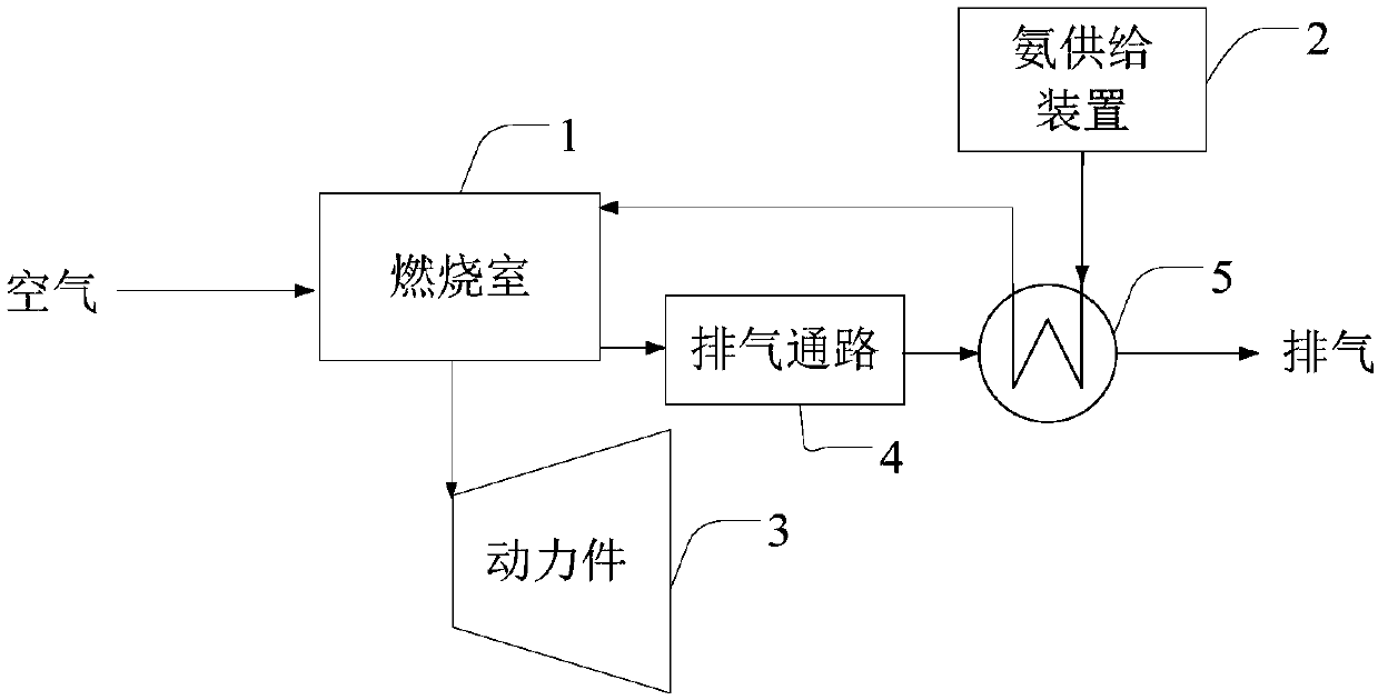
[0033] like figure 2The shown combined power and water supply device includes a combustion chamber 1, an ammonia supply device 2, a power member 3 and a water collection device 5, the ammonia supply device 2 can be connected to the combustion chamber 1 to supply ammonia to the combustion chamber 1, the combustion chamber 1 also receives air supply, the combustion chamber 1 is connected to the power member 3 to push the power member 3 to move through the exhaust gas generated by the combustion of the combustion chamber 1, the combustion chamber 1 has an exhaust passage 4, and the water collection device 5 is provided in the exhaust passage. 4 on and collect the water from the exhaust. The power member 3 may be a crank-link mechanism or a turbine mechanism. If the power element 3 selects a turbine mechanism, it can be coaxially matched with the compressor to form a gas turbine. In this embodiment, the ammonia supplied by the ammonia supply device 2 is liquid ammonia, and the ...
Embodiment 3
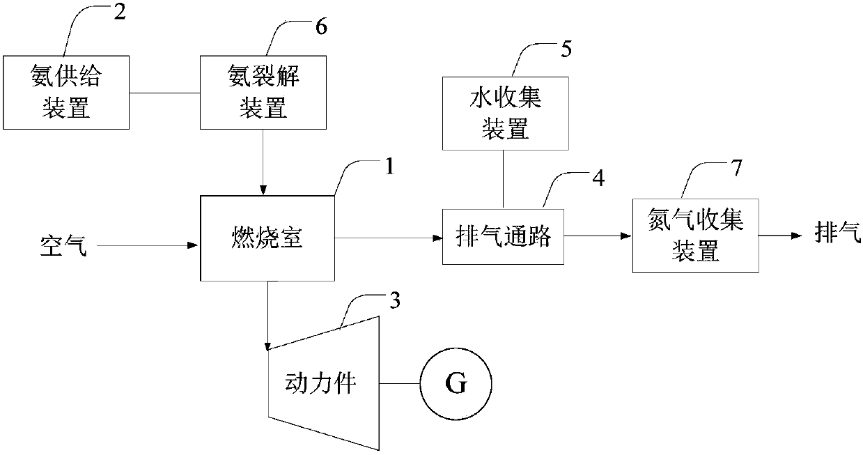
[0036] like image 3 The power and water combined supply device shown includes a combustion chamber 1, an ammonia supply device 2,
[0037] The power unit 3, the water collection device 5 and the ammonia cracking device 6, the ammonia supply device 2 is connected to the ammonia cracking device 6 to provide ammonia to the ammonia cracking device 6, the ammonia cracking device 6 decomposes ammonia and generates hydrogen, and the ammonia cracking device 6 is connected The combustion chamber supplies the combustion chamber 1 with fuel containing hydrogen. The combustion chamber 1 also receives air supply, the combustion chamber 1 is connected to the power element 3 to push the power element 3 to move through the exhaust gas generated by the combustion of the combustion chamber 1 , and the power element 3 drives the generator 9 to output electrical energy. The combustion chamber 1 has an exhaust passage 4, and the water collecting device 5 is provided in the exhaust passage 4 and ...
PUM
 Abstract
Description
Claims
Application Information
 - R&D Engineer
- R&D Manager
- IP Professional
- Industry Leading Data Capabilities
- Powerful AI technology
- Patent DNA Extraction
Browse by: Latest US Patents, China's latest patents, Technical Efficacy Thesaurus, Application Domain, Technology Topic.
© 2024 PatSnap. All rights reserved.Legal|Privacy policy|Modern Slavery Act Transparency Statement|Sitemap