Medical electronic endoscope with built-in power source
An electronic endoscope and light source technology, which is applied in optics, telescopes, optical components, etc., can solve problems such as increasing the difficulty and cost of endoscopes, increasing the burden on doctors, and attenuating signal light intensity, so as to suppress attenuation and stray light Generate, improve electrical safety, achieve the effect of repeated use
- Summary
- Abstract
- Description
- Claims
- Application Information
AI Technical Summary
Problems solved by technology
Method used
Image
Examples
Embodiment 1
[0066] Example 1: Lighting Unit
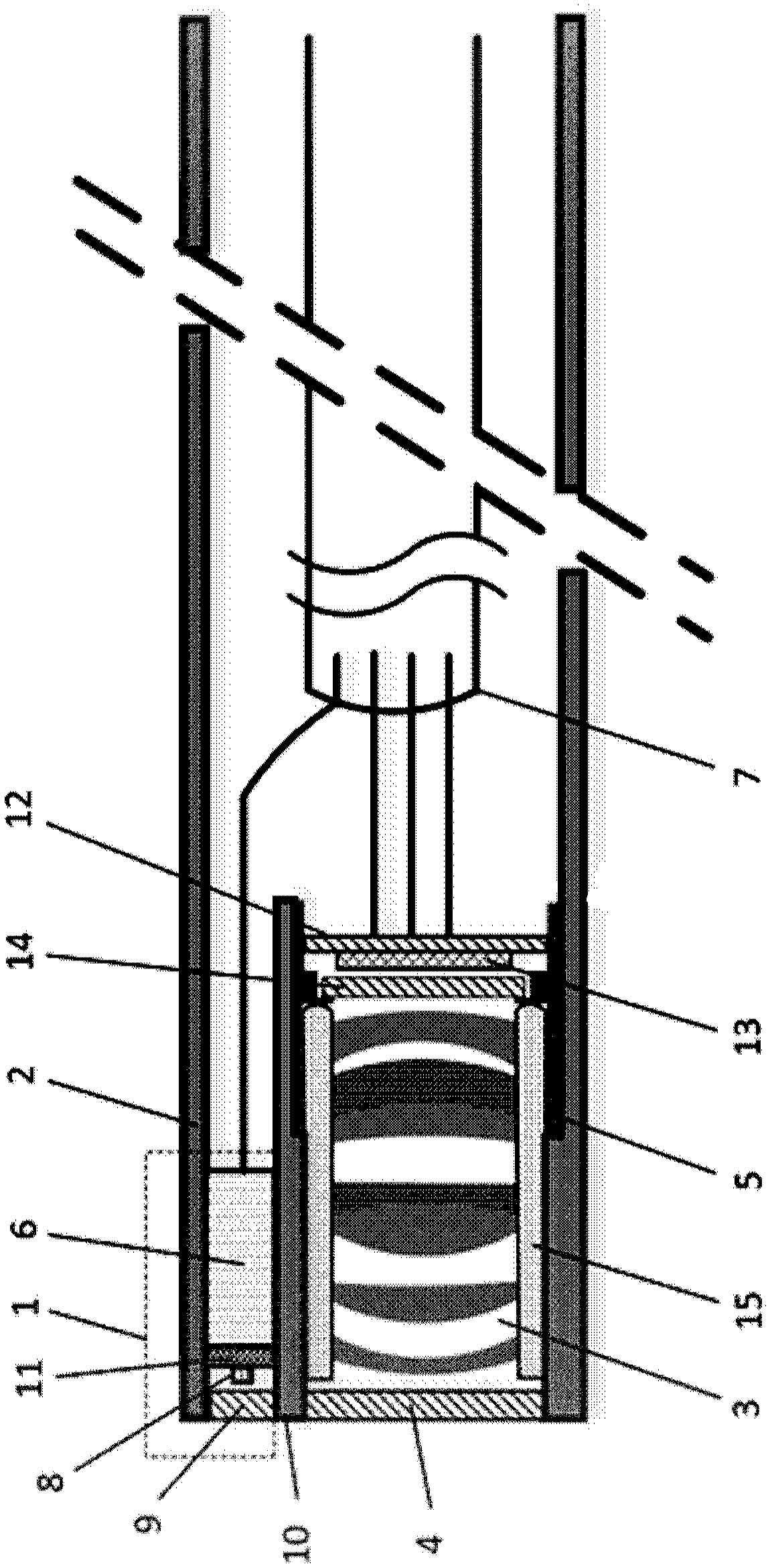
[0067] Such as figure 1 As shown, this embodiment describes the lighting unit 1 of the present invention in detail. The medical electronic endoscope of the present invention is tubular, and the lighting unit 1 is arranged in the mirror tube 2 of the medical electronic endoscope, and is opposite to the imaging lens 3 The central axis of the mirror tube 2 is arranged in parallel, and the light emitted by the light source uniformly illuminates the target area targeted by the medical electronic endoscope through the lighting window 9 .
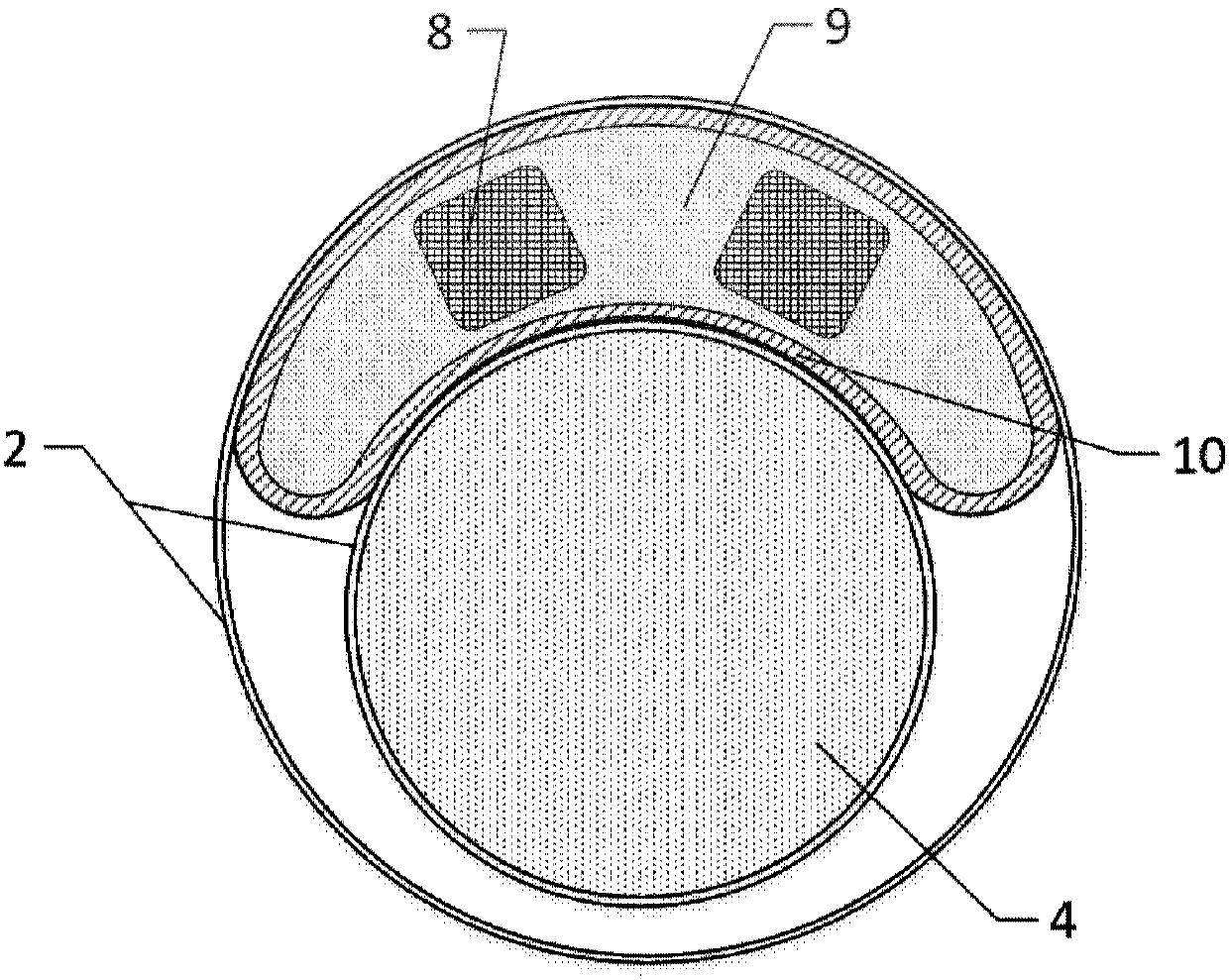
[0068] Such as figure 2 As shown, the lighting window 9 is a half-moon structure, and the lighting unit 1 is located on one side of the imaging window 4, so that the imaging window 4 is designed eccentrically, making full use of the tube space with an inner diameter of ≤10 mm.
[0069] The lighting window 9 adopts aluminum-free glass with light transmittance ≥ 98% as the substrate, such as fused silica, to ensu...
Embodiment 2
[0073] Embodiment 2: photoelectric conversion unit
[0074] This embodiment describes the imaging unit of the present invention in detail, as figure 1 As shown, the photoelectric conversion unit is located at the front end of the endoscope mirror tube 2, along the optical axis direction from the detected object, the imaging window 4, the imaging lens 3, the infrared cut filter 14, the photosensitive element 13, the PCB board 12, the line Cable 7, the optical signal collected by the imaging lens 3 is converted into an electrical signal of a static image or video, and is output to the rear end of the mirror tube 2 through the cable;
[0075] The imaging window 4 uses aluminum-free glass with light transmittance ≥ 98% as the substrate, such as fused silica, to ensure that the film layer has high adhesion on the glass substrate, so that the film layer can be sterilized by cyclic autoclaving.
[0076] The outer surface of the imaging window 4 facing the lighting area is coated wit...
Embodiment 3
[0081] Embodiment 3: Electrostatic shielding structure
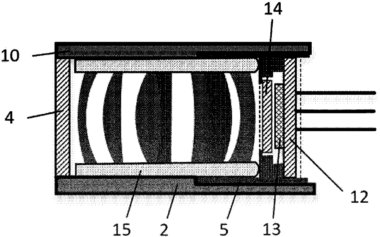
[0082] This embodiment is on the basis of embodiment 2, combining image 3 The electrostatic shielding design of the endoscope imaging system in Embodiment 2 is described in detail.
[0083] The imaging lens 3 is fixed on the imaging mirror base 5 in the mirror tube 2. The imaging mirror base 5 is resistant to 134°C cycle autoclaving, has good biocompatibility, and has a volume resistance of ≥10 at room temperature. 15 The plastic material of the order of Ω·cm, that is, made of PEEK material, prevents the leakage current of the electronic endoscope from flowing directly to the PCB board 12 of the photosensitive element 13 through the imaging mirror base 5 when the electronic endoscope is working, causing the abnormal function of the imaging unit PCB board 12 Even damage the PCB board 12 .
[0084] The non-photosensitive area of the blue glass sheet 14 in the imaging unit is fully bonded on the mirror base 5 by adhesi...
PUM
 Abstract
Description
Claims
Application Information
 - R&D
- Intellectual Property
- Life Sciences
- Materials
- Tech Scout
- Unparalleled Data Quality
- Higher Quality Content
- 60% Fewer Hallucinations
Browse by: Latest US Patents, China's latest patents, Technical Efficacy Thesaurus, Application Domain, Technology Topic, Popular Technical Reports.
© 2025 PatSnap. All rights reserved.Legal|Privacy policy|Modern Slavery Act Transparency Statement|Sitemap|About US| Contact US: help@patsnap.com


