Chemical phosphorus removal automatic control device and control method implemented by same

An automatic control device, chemical phosphorus removal technology, applied in chemical instruments and methods, water pollutants, water/sewage treatment, etc., can solve the problems of cost increase, difficulty in phosphorus removal, large floor area, etc., and is not easy to deform Effects of clogging, accelerated separation speed, and small footprint

Inactive Publication Date: 2018-03-13
浙江省围海建设集团股份有限公司
View PDF2 Cites 0 Cited by
  • Summary
  • Abstract
  • Description
  • Claims
  • Application Information

AI Technical Summary

Problems solved by technology

Among them, the biological phosphorus removal device, due to the long cultivation period of biological bacteria, and is easily affected by the anaerobic biological environment, water quality and other environmental factors, the total phosphorus removal rate is often unstable
From an economic point of view, it is difficult to use a single membrane technology to remove phosphorus, and the membrane technology is only suitable for specific phosphorus compounds and specific sewage sources, which has relatively large limitations.
The efficiency of the chemical phosphorus removal device is higher than that of the biological phosphorus removal device, and it is stable and reliable. Generally, the total phosphorus content of the effluent can meet the discharge requirement of less than 1 mg / L. However, the existing chemical phosphorus removal device is scattered due to its imperfect process , covers a large area, and the amount of chemical added is unstable, which leads to an increase in cost. It is difficult to control stably and the back-end effect is not good.

Method used


Image

  • Chemical phosphorus removal automatic control device and control method implemented by same
  • Chemical phosphorus removal automatic control device and control method implemented by same
  • Chemical phosphorus removal automatic control device and control method implemented by same

Examples


Embodiment 1

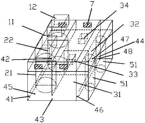
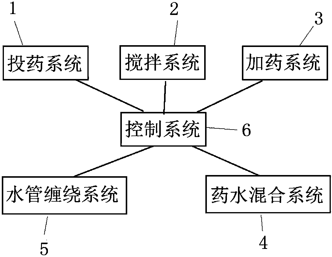
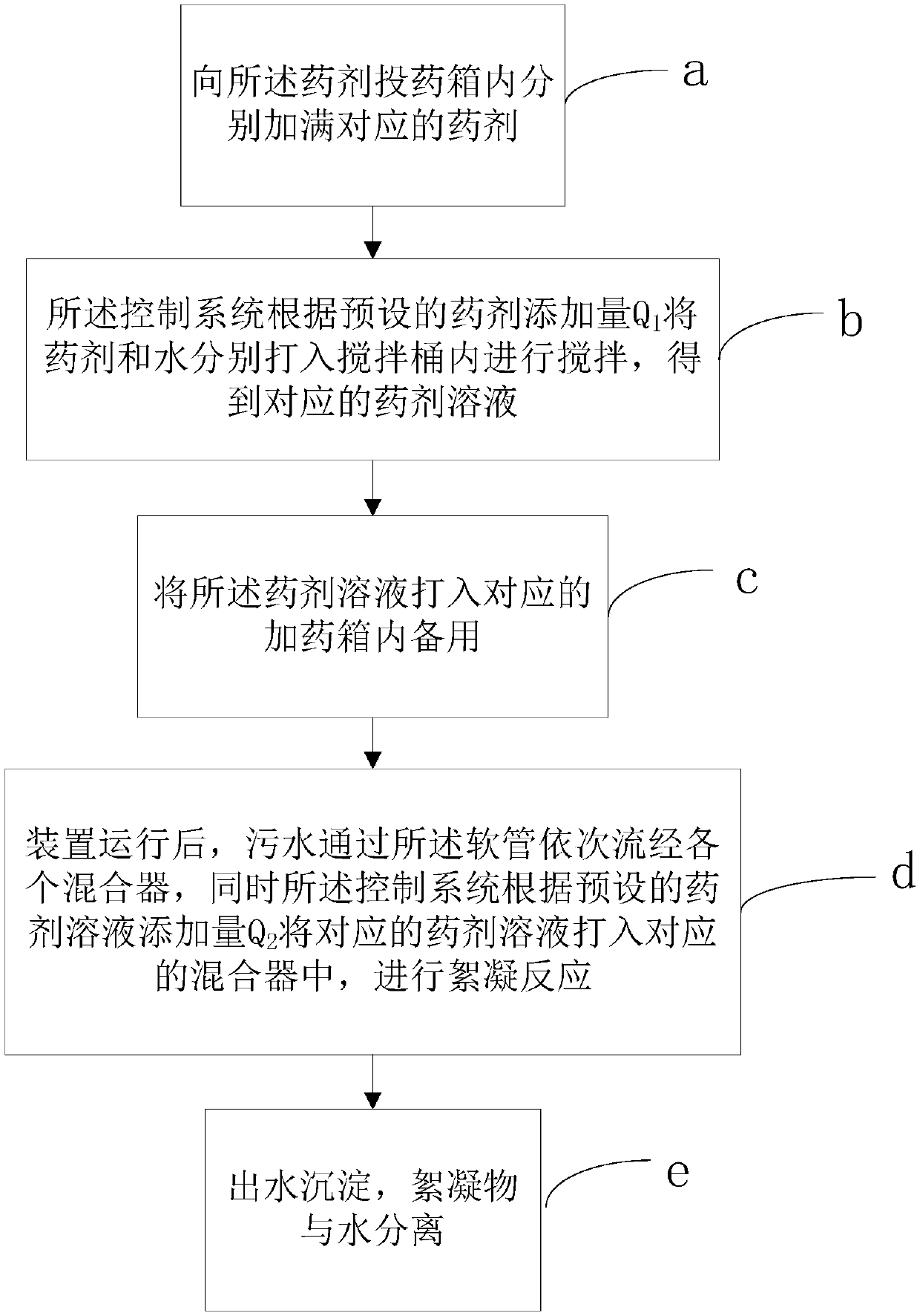
[0029] see Figure 1 to Figure 4 As shown, it is the control diagram of the automatic control device for chemical phosphorus removal of the present invention, the structural diagram of the automatic control device for chemical phosphorus removal in Embodiment 1, the flow chart of the control method of the automatic control device for chemical phosphorus removal, and the chemical phosphorus removal in Embodiment 1 Control flow chart of automatic control device.

[0030] combine figure 1 and figure 2 As shown, a chemical phosphorus removal automatic control device includes a box body and a dosing system 1, a stirring system 2, a dosing system 3, a medicine water mixing system 4, a water pipe winding system 5 and a control system 6 arranged in the box body The dosing system 1 includes several medicament dosing boxes, which are respectively used to place different medicaments, the medicament dosing box is provided with a medicament metering pump and a flow meter, and the medica...

Embodiment 2

[0042] A chemical phosphorus removal automatic control device as described above, the difference of this embodiment is that, as figure 2 As shown, the box body is provided with a heat dissipation vent 7, which is used to discharge the heat in the box body, and the number of heat dissipation vents 7 in this embodiment is four, which are respectively arranged in the box The two sides of the top help to dissipate the heat generated by the suction pump, stirring motor and dosing pump and other equipment during the operation of the device, so as to improve the safety of the device and reduce the failure rate.

Embodiment 3

[0044] The above-mentioned automatic control device for chemical phosphorus removal, the difference between this embodiment and the first embodiment lies in that the preset amount of medicament added to each mixing tank Q 1 are not the same, the dosage Q of the medicament 1 The calculation formula is:

[0045] Q 1 =a×b%

[0046] Among them, Q 1 is the added amount of the medicament, a is the added amount of water, b% is the concentration ratio of the medicament and water, and the range of b% is 1%-2% or 0.5‰-1‰.

[0047] The preset addition amount Q of medicament solution added in each said mixer 2 are not the same, the addition amount of the medicament solution Q 2 The calculation formula is:

[0048] Q 2 =c×d%

[0049] Among them, Q 2 is the added amount of the chemical solution, c is the added amount of sewage, d% is the concentration ratio of the chemical solution and sewage, and the range of d% is 3‰~1%.

[0050] As mentioned above, the sewage is stably added wi...


PUM


Abstract

The invention provides a chemical phosphorus removal automatic control device and a control method implemented by the same. The chemical phosphorus removal automatic control device comprises a tank, achemical dosing system, a stirring system, a chemical feeding system, a chemical and water mixing system, a water pipe winding system and a control system. The chemical dosing system, the stirring system, the chemical feeding system, the chemical and water mixing system and the water pipe winding system comprise chemical dosing tanks, stirring barrels, chemical feeding tanks, mixers and hoses which are sequentially connected with one another, and devices can be operated under the intelligent control of the control system. The control method implemented by the chemical phosphorus removal automatic control device includes filling the chemical dosing tanks with chemicals; feeding the chemicals and water into the stirring barrels according to preset chemical additive volumes and stirring thechemicals and the water; feeding chemical solution into the chemical dosing tanks; operating the devices, allowing sewage to flow through the mixers, feeding the chemical solution into the mixers according to preset chemical solution additive volumes and carrying out reaction; precipitating discharged water and separating flocculate from the water. The chemical phosphorus removal automatic controldevice and the control method have the advantages that accessories of the chemical phosphorus removal automatic control device are concentrated, the chemical phosphorus removal automatic control device is small in occupied area, the chemicals can be added under the automatic control, the additive volumes are stable, and the cost can be reduced.

Description

technical field [0001] The invention relates to the technical field of sewage treatment, in particular to an automatic control device for chemical phosphorus removal and a control method thereof. Background technique [0002] With the improvement of people's living standards, a large amount of phosphorus-containing domestic sewage and industrial wastewater are discharged into rivers, lakes and seas, which increases the load of nutrients in the water body, causing abnormal reproduction of algae and aquatic plants in the water body, that is, eutrophication of the water body. Excess phosphorus can also harm the marine environment and cause red tides. The research and application of phosphorus removal technology has a history of more than 20 years. The main methods of phosphorus removal in wastewater include: biological method, chemical precipitation method, physical adsorption method, membrane technology treatment method and so on. [0003] With the support of phosphorus remov...

Claims


Application Information

Patent Timeline
IPC IPC(8): C02F1/52
CPCC02F1/5209C02F2101/105
Inventor 俞元洪王杰谢士猛姜欢悦
Owner 浙江省围海建设集团股份有限公司
Why Eureka
Try Eureka