Recovery system and method for desulfurizing agent in desulfurized gas of catalytic-cracking regeneration waste gas

A catalytic cracking and exhaust gas desulfurization technology, applied in chemical instruments and methods, gas treatment, separation methods, etc., can solve problems such as high probability of gas condensation, blockage of pipelines and equipment, pollution, etc., to achieve less environmental pollution and reduce emissions Loss, the effect of reducing environmental pollution

Active Publication Date: 2018-03-27
BEIJING CREDITCONGRUITY ENERGY TECH CO LTD
View PDF14 Cites 2 Cited by
  • Summary
  • Abstract
  • Description
  • Claims
  • Application Information

AI Technical Summary

Problems solved by technology

However, due to the fact that the solid dust carried in the hot flue gas is easy to deposit in the regenerator, this technology causes blockage and operation problems; and heating the gas at the outlet of the desulfurization tower cannot effectively reduce the dew point of the gas. On the one hand, the water vapor entrained in the gas and the desulfurization The agent will still be lost in a large amount, causing pollution after entering the atmosphere. On the other hand, the probability of condensation of the gas in a lower temperature environment is still high, and it is easy to corrode and deposit to block pipes and equipment.

Method used


Image

  • Recovery system and method for desulfurizing agent in desulfurized gas of catalytic-cracking regeneration waste gas

Examples


Embodiment 1

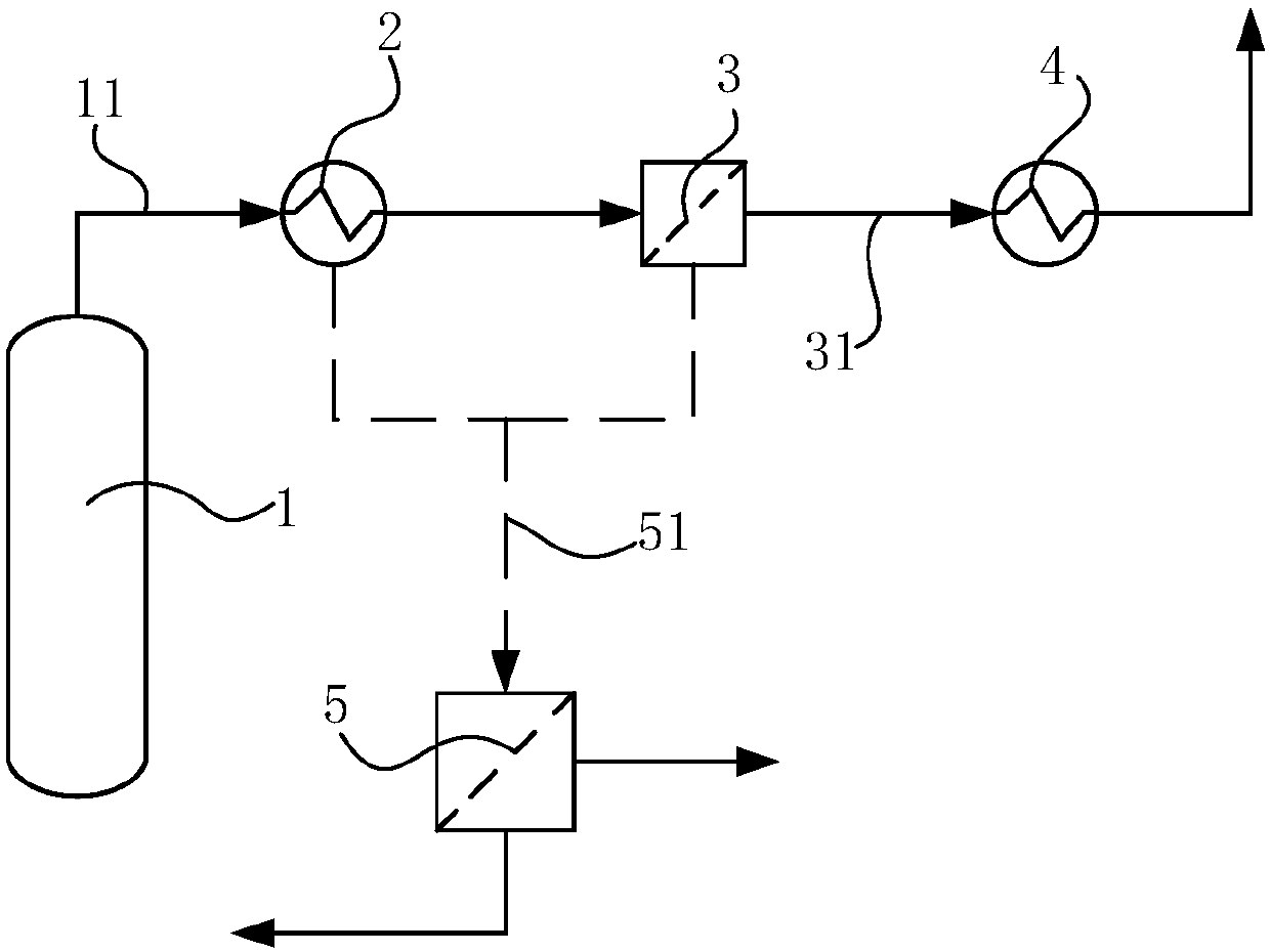
[0055] 30000m 3 / h Catalytic cracking regenerated exhaust gas, after desulfurization through the desulfurization tower by sodium alkali method, the obtained desulfurized gas has a temperature of 50-55°C, and is cooled by 3°C through a condensing heat exchanger to obtain a cooled gas with a temperature of 47-52°C. The cooling gas passes through a screen-type mechanical separation purifier to separate the liquid droplets and solid particles in the cooling gas to obtain purified gas; the slurry separated from the cooling gas and the condensed water generated by the condensing heat exchanger form a slurry together, The filtered filtrate containing desulfurization agent is returned to the desulfurization tower for further use. The purified gas finally enters the heating heat exchanger for heating, and is discharged after the temperature rises by 5°C. The condensing heat exchanger is a plate-fin heat exchanger made of titanium alloy, and the windward side of the plate-fin heat exch...

Embodiment 2

[0057] 50000m 3 / h Catalytic cracking regenerated exhaust gas, after desulfurization through the desulfurization tower by calcium method, the obtained desulfurized gas temperature is 50-55°C, cooled by 20°C through the condensing heat exchanger to obtain the cooling gas with a temperature of 30-35°C. The cooling gas passes through a screen-type mechanical separation purifier to separate the liquid droplets and solid particles in the cooling gas to obtain purified gas; the slurry separated from the cooling gas and the condensed water generated by the condensing heat exchanger form a slurry together, The filtered filtrate containing desulfurization agent is returned to the desulfurization tower for further use. The purified gas finally enters the heating heat exchanger for heating, and is discharged after the temperature rises to 40°C. The condensing heat exchanger is a plate-fin heat exchanger made of duplex stainless steel, and there are ceramic sheets on the windward side of...

Embodiment 3

[0059] 50000m 3 / h Catalytic cracking regenerated exhaust gas, after desulfurization treatment through the desulfurization tower by ammonia method, the obtained desulfurized gas has a temperature of 70-80°C, and is cooled by 40°C through a condensing heat exchanger to obtain a cooled gas with a temperature of 30-40°C. The cooling gas is passed through a grid-type mechanical separation purifier to separate the liquid droplets and solid particles in the cooling gas to obtain purified gas; the slurry separated from the cooling gas and the condensed water generated by the condensing heat exchanger form a slurry together. The filtered filtrate containing desulfurization agent is returned to the desulfurization tower for further use. The purified gas finally enters the heating heat exchanger for heating, and is discharged after the temperature rises to 45°C. The condensing heat exchanger is a plate heat exchanger made of austenitic stainless steel, with enamel sheets on the windwar...


PUM


Abstract

The invention relates to a recovery system and method for a desulfurizing agent in a desulfurized gas of a catalytic-cracking regeneration waste gas. The recovery system comprises a desulfurizing tower, a condensing heat exchanger, a mechanical separation purifier, a heating heat exchanger and a filter, wherein a gas outlet of the desulfurizing tower is communicated with a gas inlet of the mechanical separation purifier through a first pipeline; the condensing heat exchanger is mounted in the first pipeline; the heating heat exchanger is mounted in a gas exhaust pipeline of the mechanical separation purifier; the condensing heat exchanger and the mechanical separation purifier are communicated with the filter respectively through second pipelines. The recovery system can be used for effectively decreasing the dew point of an outlet gas from the desulfurizing tower, is used for decreasing water vapor content and the particle concentrations of entrained desulfurizing agent and catalyst in the outlet gas, can be used for recovering most of the desulfurizing agent, and is used for decreasing the discharge loss of the desulfurizing agent, decreasing a running cost and meanwhile reducingenvironment pollution; through arranging the heating heat exchanger, an exhausted gas can be prevented from entering an environment of which temperature is lower than the temperature of the gas so that a liquid drop can be still immediately condensed and the formation of a rime fog is prevented.

Description

technical field [0001] The invention relates to the technical field of environmental protection technology, in particular to a system and method for recovering a desulfurizer in gas after desulfurization of catalytic cracking regenerated waste gas. Background technique [0002] Catalytic cracking is an important process in oil refining production. Catalysts for catalytic cracking need to be periodically regenerated, and the waste gas generated during the regeneration process contains pollutants such as sulfur dioxide, which need to be purified by a desulfurization process before being discharged. Desulfurization generally adopts a wet desulfurization process. The desulfurization agent is lye, and the desulfurization agent contacts with the gas and reacts with sulfur dioxide to remove the sulfur dioxide in the gas. The lye can be lime, sodium hydroxide or sodium carbonate, ammonia, etc., and the corresponding desulfurization processes are called calcium desulfurization, sodi...

Claims


Application Information

Patent Timeline
Patent Type & Authority Applications(China)
IPC IPC(8): B01D53/96B01D53/50B01D53/78B01D53/00B01D53/26
CPCB01D53/002B01D53/26B01D53/50B01D53/78B01D53/96B01D2258/02
Inventor 林峰尹晔东
Owner BEIJING CREDITCONGRUITY ENERGY TECH CO LTD
Why Eureka
Try Eureka