Nitrogen and phosphorus removal integrated device

A technology for nitrogen and phosphorus removal and equipment, applied in anaerobic digestion treatment, chemical instruments and methods, water/sludge/sewage treatment, etc. Unstable operation and other problems, to achieve the effect of sludge resource utilization and stable utilization, optimization of effluent water quality, and improvement of sedimentation performance

Inactive Publication Date: 2018-03-30
湖南千幻科技有限公司
View PDF0 Cites 0 Cited by
  • Summary
  • Abstract
  • Description
  • Claims
  • Application Information

AI Technical Summary

Problems solved by technology

[0003] Due to the unsound sewage collection facilities in our country, rainwater and sewage flow into the drainage system, resulting in the low C / N ratio of the influent water quality of urban sewage treatment plants in my country. When the carbon-nitrogen ratio is lower than the minimum value required for complete denitrification, Incomplete denitrification reaction will occur, which will affect the efficiency of nitrogen and phosphorus removal
Moreover, due to excessive aeration, surfactant action or denitrification reaction, micro-bubbles are generated, which reduces the density of the sludge, causing the sludge to float and generate foam, which affects the sedimentation and biochemical performance of the sludge. Therefore, it is necessary to use physical, Chemical and other methods reduce the formation of foam, but there are problems such as secondary pollution, unstable operation, and high operating costs
On the other hand, there are a large number of toxic and refractory pollutants in the sewage, which are wrapped on the surface of activated sludge flocs for a long time and cannot be degraded or detached, resulting in mass transfer obstruction, resulting in nitrifying or denitrifying bacteria not being able to obtain nutrient supply in time and causing bacterial biochemical performance. become worse
In addition to the problems of hindered mass transfer of sludge and low efficiency of nitrogen and phosphorus removal, problems such as large surplus sludge production and difficulty in resource treatment are also major problems faced by existing sewage treatment

Method used


Image

  • Nitrogen and phosphorus removal integrated device

Examples


Embodiment Construction

[0015] In order to make the object, technical solution and advantages of the present invention clearer, the present invention will be further described in detail below in conjunction with the accompanying drawings and embodiments. It should be understood that the specific embodiments described here are only used to explain the present invention, not to limit the present invention.

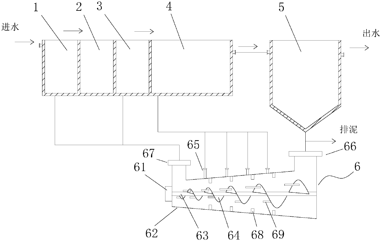
[0016] see figure 1 , figure 1 It is a structural schematic diagram of the present invention.

[0017] An integrated equipment for nitrogen and phosphorus removal includes a pre-anoxic pool 1, an anaerobic pool 2, an anoxic pool 3, an aerobic pool 4, a sedimentation pool 5, and a sludge separator 6; the pre-anoxic pool 1, anaerobic pool Oxygen tank 2, anoxic tank 3, aerobic tank 4, and sedimentation tank 5 are connected successively; the pre-anoxic tank 1 is provided with a water inlet, and the sedimentation tank 5 is provided with a water outlet and a sludge outlet; the sludge The separator 6 i...


PUM


Abstract

The invention discloses a nitrogen and phosphorus removal integrated device, which comprises a pre-anoxic pond, an anaerobic pool, an anoxic pond, an aerobiotic pond, a sediment pond, and a sludge separator; the sludge separator comprises a sludge separator main body, a stirring motor, a stirring shaft, and a spiral blade; the spiral blade is arranged on the stirring shaft, and the screw space ofthe spiral blade is gradually reduced from the mud inlet side to the mud outlet side. When sludge moves forwards in the sludge separator main body, the inner part of the sludge separator main body generates great inner pressure along with gradually reduced screw space of the spiral blade, and the sludge volume is continuously reduced; for the gas density is much less than that of the sludge floc,gas is discharged from an overflow opening to the aerobiotic pond; thus the oxygen deficiency environments of the pre-anoxic pond, the anaerobic pool, and the anoxic pond are guaranteed during the degasing process, the sludge settling performance is improved; the sludge expansion, floating and bubble generation are controlled, and effluent quality is optimized.

Description

technical field [0001] The invention relates to the technical field of sewage treatment, in particular to an integrated equipment for nitrogen and phosphorus removal. Background technique [0002] With the acceleration of urban development and industrialization, sewage treatment has become a hot environmental issue that people focus on. A large amount of domestic sewage, industrial wastewater and farmland surface water runoff flow into lakes, rivers, reservoirs and bay waters, causing algae and other plants to multiply, thus forming water body eutrophication. For a country like my country that is already short of water resources, it is necessary to strictly control the excessive discharge of nitrogen and phosphorus sewage. The nitrogen and phosphorus removal technology in the prior art mainly adopts the anaerobic / anoxic / aerobic biochemical process (AAO process), and uses the principle of nitrification / denitrification to perform simultaneous decarburization, phosphorus remov...

Claims


Application Information

Patent Timeline
IPC IPC(8): C02F9/14C02F3/30C02F3/28C02F101/16C02F101/10
CPCC02F3/30C02F3/286C02F2001/007C02F2101/105C02F2101/16
Inventor 不公告发明人
Owner 湖南千幻科技有限公司
Why Eureka
Try Eureka