Microwave multi-spiral pyrolyzation equipment

A multi-screw and microwave technology, applied in lighting and heating equipment, combustion methods, combustion types, etc., can solve the problems of feeder number and area limitation, inability to handle materials, low production capacity, etc., to improve heating safety and structural design Reasonable, rapid pyrolysis effect

Pending Publication Date: 2018-04-06
NANJING SANLE MICROWAVE TECH DEV +2
View PDF0 Cites 4 Cited by
  • Summary
  • Abstract
  • Description
  • Claims
  • Application Information

AI Technical Summary

Problems solved by technology

[0002] Conventional energy pyrolysis equipment mainly uses conventional energy sources (such as electricity, coal, gas, etc.) to heat up the furnace body by externally heating the furnace body. Conventional energy sources have low heat conversion efficiency (generally, the heat utilization efficiency is only 30~ 40%), slow aging, high energy consumption, and the emissions after conventional energy combustion will cause secondary pollution
[0003] Conventional energy pyrolysis equipment has a small processing capacity when dealing with oily solid waste produced in oil field exploitation, and the open flames generated by external heating have great safety hazards and the equipment furnace is easily coked.
[0004] The existing microwave rotary furnace equipment has a low material filling rate, generally only 6% to 15%, resulting in low production capacity
The existing microwave rotary kiln equipment has a microwave source that can only feed microwave energy from one direction of the kiln head, and the number and area of ​​feed ports are greatly limited, resulting in uneven microwave field and low heating efficiency
Existing rotary kiln equipment is generally atmospheric equipment and the airtightness between the kiln head and the kiln body is poor. The inside of the furnace body cannot isolate oxygen from contact with the material, and cannot handle materials with dangerous gas volatilization, which may catch fire or even explode. Security Risk

Method used


Image

  • Microwave multi-spiral pyrolyzation equipment

Examples


Embodiment Construction

[0032] Below in conjunction with accompanying drawing and specific embodiment, further illustrate the present invention, should be understood that these embodiments are only for illustrating the present invention and are not intended to limit the scope of the present invention, after having read the present invention, those skilled in the art will understand various aspects of the present invention Modifications in equivalent forms all fall within the scope defined by the appended claims of this application.

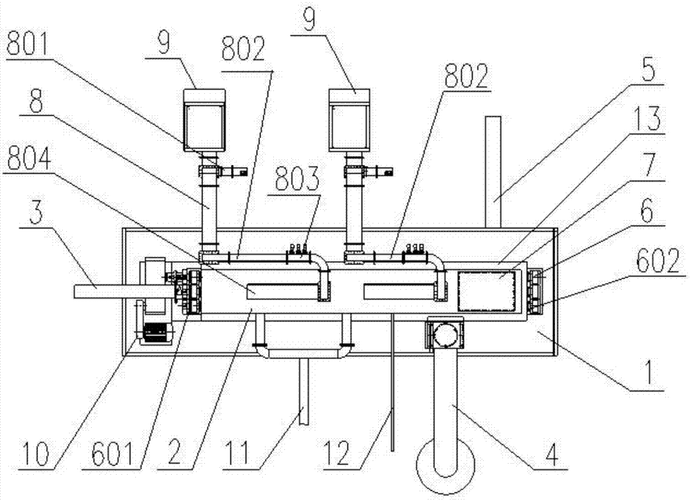
[0033] Such as figure 1 Shown, a kind of microwave multi-helical pyrolysis equipment, it comprises frame 1, the microwave pyrolysis chamber 2 that is installed on the frame 1, feed pipeline 3 that links to each other with microwave pyrolysis chamber 2, explosion venting system 4, outlet Material pipeline 5, exhaust pipeline 11 and nitrogen flushing pipeline 12; Furnace door 7 is installed on described microwave pyrolysis chamber 2, and microwave pyrolysis chamber 2 is co...


PUM


Abstract

The invention discloses a microwave multi-helix pyrolysis device, which comprises a frame (1), a microwave pyrolysis chamber (2) installed on the frame (1), and a feeding material connected to the microwave pyrolysis chamber (2). pipeline (3), explosion venting system (4), discharge pipeline (5), exhaust pipeline (11) and nitrogen flushing pipeline (12); a furnace door (7) is installed on the microwave pyrolysis chamber (2), and microwave The pyrolysis chamber (2) is connected to the microwave transmission system (8), the microwave transmission system (8) is connected to the microwave energy generator (9), the microwave pyrolysis chamber (2) is connected to the multi-screw conveying system (6), and the multi-screw The conveying system (6) is driven to rotate by a motor (10). The design of the structure is reasonable, the microwave radiation is uniform, the heating efficiency is high, it can be heated to 800°C, and the sealing and oxygen barrier are good. .

Description

technical field [0001] The invention belongs to the technical field of microwave heating, and in particular relates to a microwave multi-helix pyrolysis device. The invention is used for medium-high temperature microwave heating of materials, and the temperature range can reach 800 ° C. It is especially suitable for the treatment of materials containing organic solvents. It is mainly used in the treatment of oily solid waste generated during oilfield mining, and can also be used in the regeneration of activated carbon after adsorption and Soil improvement and other environmental protection projects. Background technique [0002] Conventional energy pyrolysis equipment mainly uses conventional energy sources (such as electricity, coal, gas, etc.) to heat up the furnace body by externally heating the furnace body. Conventional energy sources have low heat conversion efficiency (generally, the heat utilization efficiency is only 30~ 40%), slow aging, high energy consumption, a...

Claims


Application Information

Patent Timeline
Patent Type & Authority Applications(China)
IPC IPC(8): F23G5/027F23G5/44F23G5/50
CPCF23G5/0273F23G5/44F23G5/50F23G2201/302F23G2204/203
Inventor 奚伟麟刘林春郑瑛琦康新蕾杨琦邱林
Owner NANJING SANLE MICROWAVE TECH DEV
Why Eureka
Try Eureka