Method for measuring physical property of magneto-optical dielectric film under low-temperature and high-pressure condition

A magneto-optical medium, low temperature and high pressure technology, applied in the measurement of magnetic variables, the size/direction of the magnetic field, measuring devices, etc., can solve problems such as difficulties, opacity, and magnetic properties of tungsten carbides to prevent liquid pressure media Leakage, reduced probability of chipping, high conductivity effect

Pending Publication Date: 2018-04-06
JINHUA VOCATIONAL TECH COLLEGE
View PDF0 Cites 2 Cited by
  • Summary
  • Abstract
  • Description
  • Claims
  • Application Information

AI Technical Summary

Problems solved by technology

[0004] The disadvantage of the prior art is that in the method of measuring pressure by fluorescence spectroscopy in a non-atmospheric environment or a low temperature environment, an optical fiber is required to introduce light into the pressure chamber, and to couple the optical fiber to the sample pressure chamber, so that the optical fiber can efficiently transmit and It is more difficult to collect light; in the prior art, a larger diamond is usually used as an anvil, and tungsten carbide is used as a support table material, and diamond is expensive, while tungsten carbide is magnetic and opaque ; in testing the dielectric properties of fragile thin film samples under high pressure using an anvil, usually consisting of a tungsten carbide anvil, a metal press plate used as an electrode, and an electrically insulating washer
The difficulty in the prior art is that under different pressure conditions, the effective area and the distance between the electrodes are variable. In addition, due to the deformation of the gasket, it is especially difficult to estimate the effective electrode area. The method of thin film physical properties can solve the problem

Method used


Image

  • Method for measuring physical property of magneto-optical dielectric film under low-temperature and high-pressure condition

Examples


Embodiment Construction

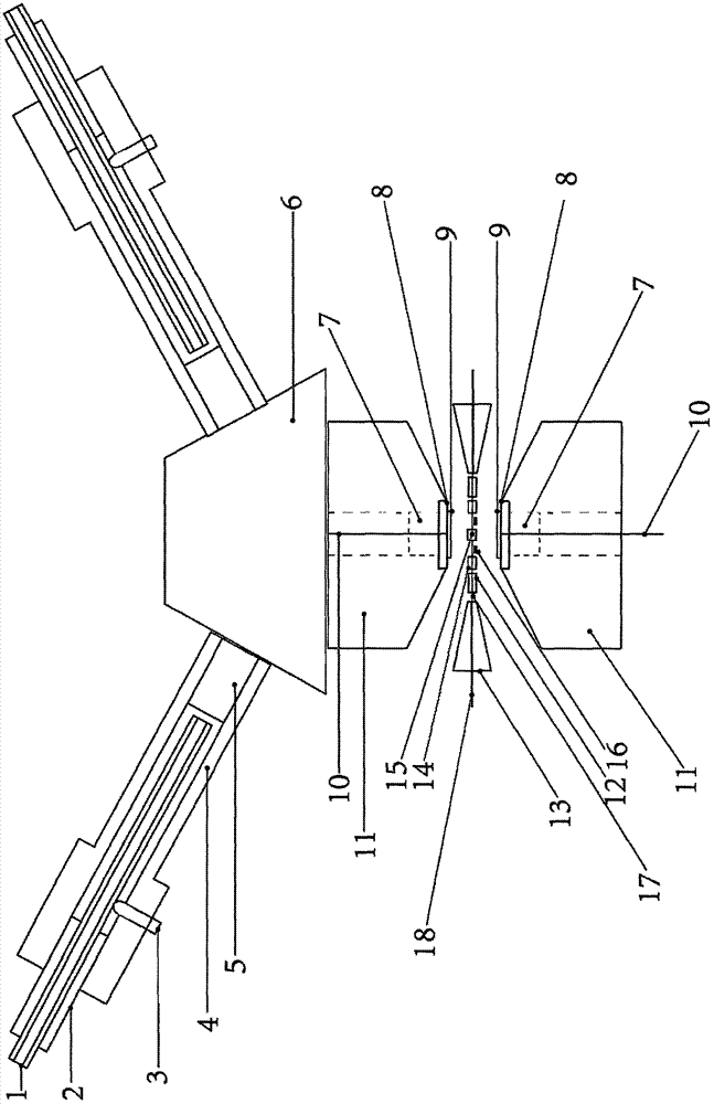
[0018] Such as figure 1It is a schematic diagram of the structure of the present invention, mainly including optical fiber (1), displacement tube (2), screw (3), sleeve (4), gradient index lens (5), silicon carbide support table (6), epoxy resin and Diamond particle mixture (7), PTFE film (8), conductive glass electrode plate (9), current lead (10), tungsten carbide anvil (11), stainless steel ring (12), aluminum gasket (13), Teflon ring (14), sample (15), support particles (16), gold wire (17), copper wire (18), magnet, laser, polarizer, photodetector, magnet for generating a magnetic field at the sample location, The tungsten carbide anvil (11) includes an upper anvil and a lower anvil, and the center of the axis has a through hole, and the epoxy resin and the diamond particle mixture (7) are filled in the holes, and are all covered in turn. The PTFE membrane (8) and the conductive glass electrode plate (9), the liquid pressure medium will not leak under high pressure, the ...


PUM

PropertyMeasurementUnit
Thicknessaaaaaaaaaa

Abstract

The invention relates to a method for measuring the physical property of a magneto-optical dielectric film under a low-temperature and high-pressure condition for high-pressure physical experiments and material physical property measurement. A sample is placed in a Teflon ring. A ruby sheet is placed beside the sample. One end of a gold wire is connected with the sample via silver glue. A liquid pressure medium is continuously added to the Teflon ring. A pressing device applies pressure to an anvil. A displacement tube and a screw are adjusted so that the relative position between an optical fiber and a gradual change refractive index lens and between an optical fiber and a silicon carbide supporting table meets an optical fiber Transmission requirement. Pressure is measured by using a ruby fluorescence method. The dielectric constant of the sample is measured. A current wire is connected to a dielectric constant meter and the dielectric constants of the sample under various anvil pressure conditions are recorded. A magnetic field is applied to the sample. A laser emitted from a laser device irradiates the surface of the sample after passing through a polarizer. The light reflectedfrom the sample surface passes through an analyzer and enters a photoelectric detector to measure a magneto-optical Kerr effect and obtain the magnetization state of the sample under different pressure conditions.

Description

technical field [0001] The invention relates to the fields of high-pressure physical experiment technology and material property measurement, and is a method for measuring the physical properties of magneto-optical medium films under low temperature and high pressure conditions, which can reduce the fragmentation rate of sample films and is suitable for extremely low temperatures. Background technique [0002] The anvil is currently the only scientific experimental device that can generate a static pressure of more than one million atmospheres. It is irreplaceable in high-pressure scientific research. The high-hardness material squeezes the sample mechanically to generate a high-pressure environment. A metal gasket with a sample hole pre-processed is placed between the extrusion surfaces formed by the two table tops, and the sample is placed in the sample hole. During the experiment, the pressure on the sample needs to be monitored. At present, the general pressure test meth...

Claims


Application Information

Patent Timeline
IPC IPC(8): G01R33/032
CPCG01R33/0325
Inventor 朱登胜徐建丽
Owner JINHUA VOCATIONAL TECH COLLEGE
Why Eureka
Try Eureka