In-situ regeneration device of SCR catalyst for household garbage burning

A technology for SCR catalysts and domestic waste incineration, which is applied in catalyst regeneration/reactivation, physical/chemical process catalysts, chemical instruments and methods, etc., and can solve the problem of decreased denitrification efficiency of SCR systems, failure to meet NOx emission requirements, and reduced catalyst service life and other problems, to achieve the effect of saving the cost of use, simplifying the regeneration steps and reducing the regeneration cost

Pending Publication Date: 2018-04-10
SHANGHAI SUS ENVIRONMENT
View PDF6 Cites 9 Cited by
  • Summary
  • Abstract
  • Description
  • Claims
  • Application Information

AI Technical Summary

Problems solved by technology

The catalyst is an important part of the SCR denitrification system. In addition to being more expensive, the catalyst is more expensive. At the operating temperature of 180 ° C ~ 230 ° C, the SO3 in the flue gas is likely to cause catalyst poisoning. SO3 comes from two parts, one part is the active component V2O5 can catalyze Oxidize SO2 to generate SO3, and the other part is SO3 contained in the flue gas. SO3 will react with NH3 to generate NH4HSO4. This kind of sulfate is cohesive and corrosive, causing the pores of the catalyst to be blocked and reducing the service life of the catalyst.
[0003] At present, the operating temperature of the SCR system in the waste incineration flue gas purification system is between 170°C and 230°C. Due to the low operating temperature, NH3 is easy to form NH4HSO4 with SO2 and SO3, which will cause the pores of the catalyst to be blocked, resulting in a decrease in the denitrification efficiency of the SCR system. , unable to meet NOx emission requirements

Method used


Image

  • In-situ regeneration device of SCR catalyst for household garbage burning
  • In-situ regeneration device of SCR catalyst for household garbage burning

Examples


Embodiment 1

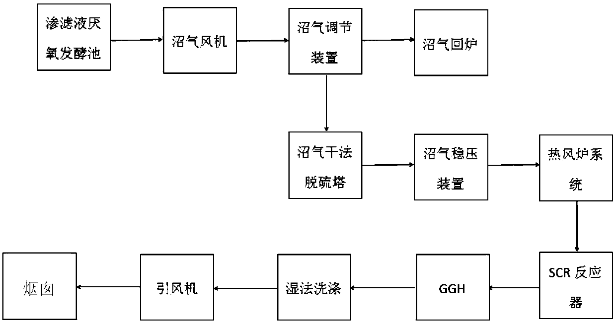
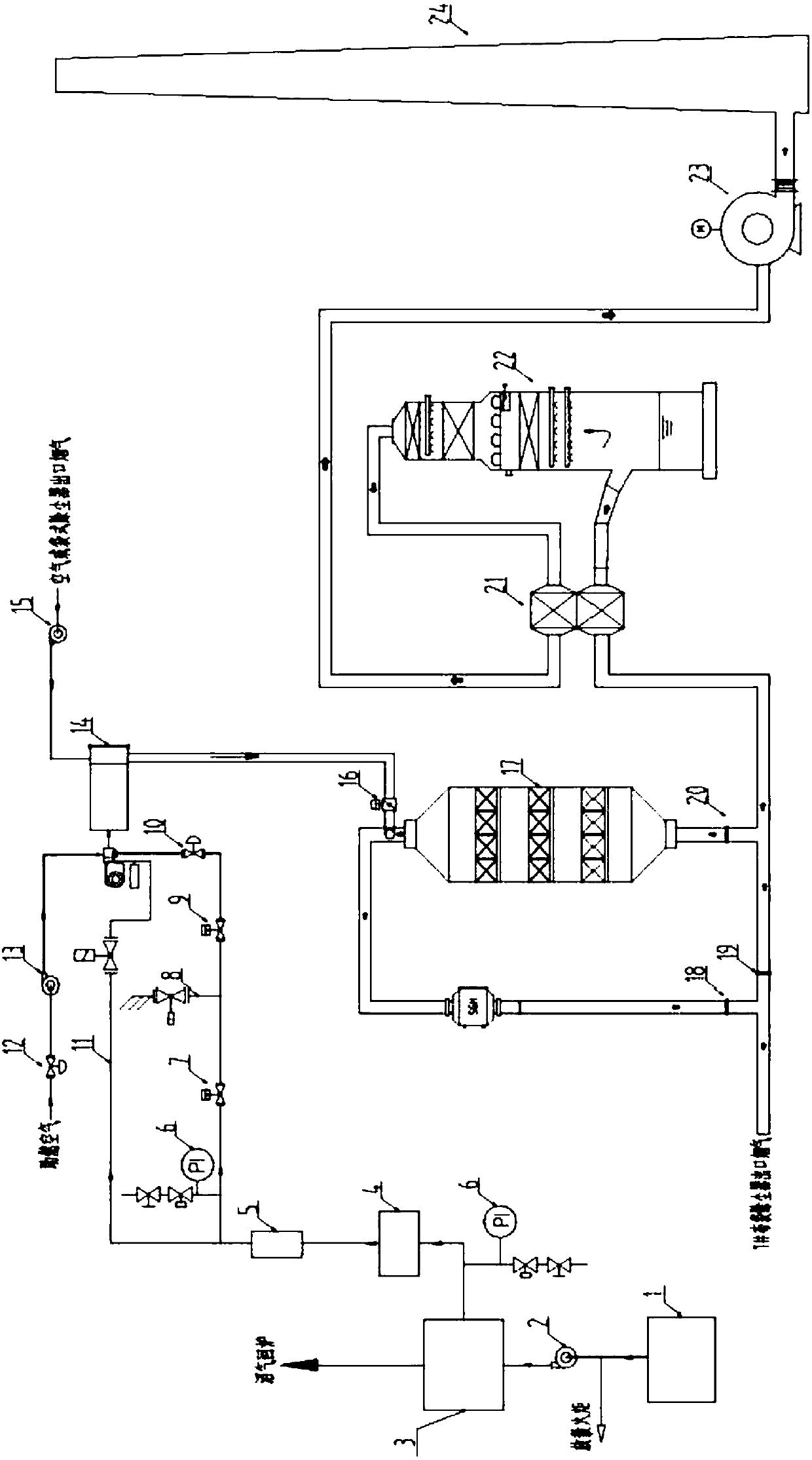
[0029] An in-situ regeneration device for SCR catalysts applied to domestic waste incineration, the schematic diagram of which is shown in Fig. figure 2 As shown, it includes anaerobic fermentation tank 1, biogas fan 2, biogas flow regulating device 3, biogas desulfurization tower 4, biogas pressure regulating device 5, nitrogen replacement device 6, biogas shut-off valve 7, biogas release solenoid valve 8, biogas shut-off valve 9. Biogas control valve 10, ignition burner 11, combustion-supporting air electric control valve 12, combustion-supporting fan 13, hot blast stove 14, secondary fan 15, regenerative flue gas electric valve 16, SCR reactor 17, SCR inlet baffle door 18 , SCR outlet baffle door 20, SCR bypass baffle door, flue gas-flue gas heat exchanger 21, wet scrubber, induced draft fan 23 and chimney 24.

[0030] The upper part of the anaerobic fermentation tank 1 is provided with a biogas outlet, and the bottom is provided with a leachate inlet;

[0031] The mouth ...


PUM


Abstract

An in-situ regeneration device of an SCR catalyst for household garbage burning comprises an anaerobic fermentation tank, a biogas blower fan, a biogas adjusting device, a biogas desulfurization tower, a combustion fan, a hot wind furnace, a secondary air fan, a regeneration flue baffle door, an SCR reactor, an SCR catalyst, a flue collector baffle door, GGH, a wet process washing tower, an induced draught fan, and a chimney. The anaerobic fermentation tank, the biogas blower fan, the biogas adjusting device, the biogas desulfurization tower, the combustion fan, the hot wind furnace, the secondary air fan, the regeneration flue baffle door, the SCR reactor, and the SCR catalyst form a catalyst regeneration system. A wet type acid removing tower removes SOx and NH3 in regenerated flue gas,and the discharged flue gas can meet the discharge standards during the regeneration period.

Description

technical field [0001] The invention relates to an in-situ regenerating device of an SCR catalyst applied to domestic waste incineration. Background technique [0002] SNCR and SCR are the main processes for treating NOx in waste incineration power plants, and the removal rate of NOx for SNCR is between 40% and 60%, and the removal rate for SCR for NOx can reach more than 90%. As the NOx emission limit requirements become more and more stringent, the local standards in some areas require the NOx emission value to be 100mg / Nm3. In order to meet the NOx emission requirements, more and more waste incineration power plants adopt the combination of SNCR and SCR denitrification process. In waste incineration plants, the SCR denitrification system is usually installed behind the bag filter, and the operating temperature is about 180°C to 230°C. The catalyst is an important part of the SCR denitrification system. In addition to being more expensive, the catalyst is more expensive. ...

Claims


Application Information

Patent Timeline
Patent Type & Authority Applications(China)
IPC IPC(8): B01J38/02B01D53/96B01D53/88B01D53/56
CPCB01D53/8631B01D53/88B01D53/96B01J38/02
Inventor 白力冯淋淋刘焕联劳云枫陆钧皓刘露孙中涛舒伟康毛梦梅瞿兆舟
Owner SHANGHAI SUS ENVIRONMENT
Why Eureka
Try Eureka