Dual-band antenna feed system and dual-band antenna

A dual-frequency antenna and feeding system technology, which is applied in the structural connection of antenna and antenna grounding switch, and the device that enables the antenna to work in different bands at the same time, can solve the problem of reducing the performance of the antenna radiation pattern, which cannot be achieved, is difficult to achieve, etc. problems, to achieve the effect of large-scale popularization and application, simple and compact structure, and low cost

Pending Publication Date: 2018-04-13
PIVOTONE COMM TECH
View PDF0 Cites 18 Cited by
  • Summary
  • Abstract
  • Description
  • Claims
  • Application Information

AI Technical Summary

Problems solved by technology

[0005] For the dual-frequency antenna that can work in E-band, the design difficulty of its feed system lies in: 1. The E-band frequency is very high, which is 4 times or even 5 times higher than the commonly used point-to-point communication frequency, the difference is so It is very difficult to implement a combiner in two large frequency bands. With the commonly used duplexer scheme, the low-frequency low-pass filter for E-band frequency signals cannot be realized in the conventional way; 2. The diameter of the feed circular waveguide commonly used for point-to-point communication It is much larger than the maximum size of the waveguide that can suppress the E-band high-order mode. Therefore, when the E-band frequency band signal is transmitted in the ordinary circular waveguide, the

Method used


Image

  • Dual-band antenna feed system and dual-band antenna
  • Dual-band antenna feed system and dual-band antenna
  • Dual-band antenna feed system and dual-band antenna

Examples


Embodiment Construction

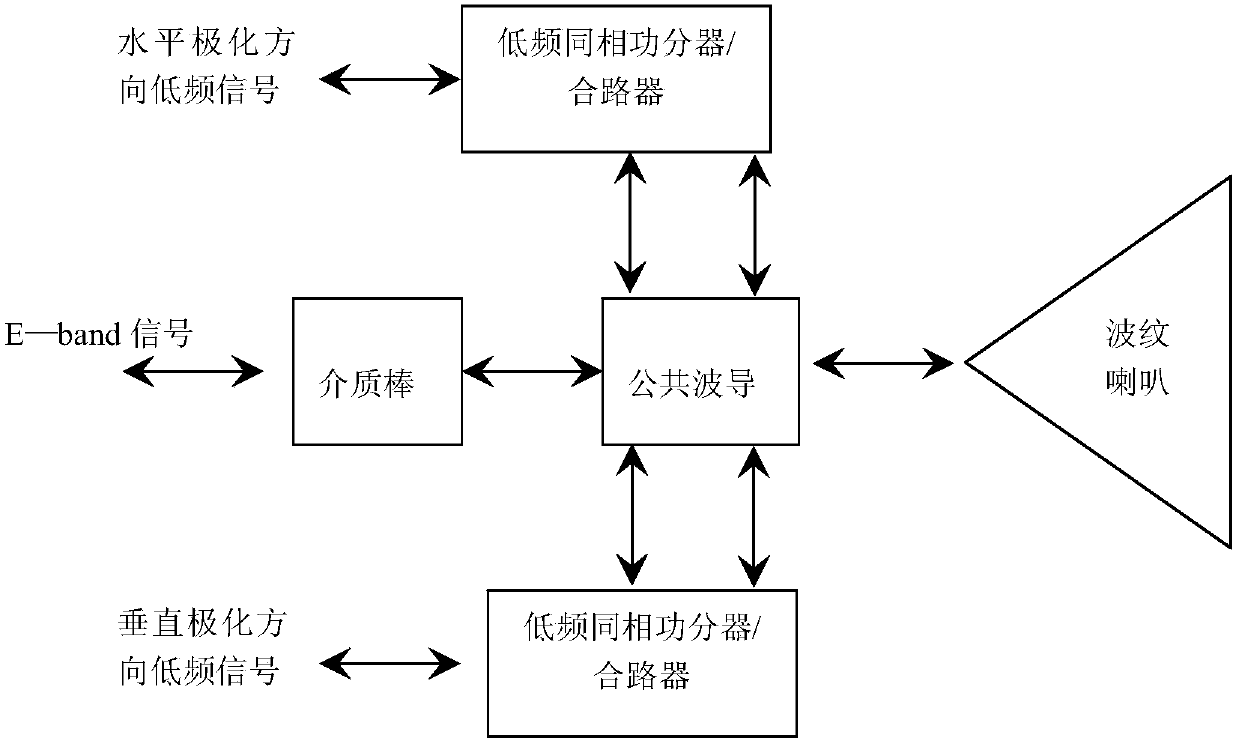
[0030] Aiming at the feeding problem of the same antenna shared by the E frequency band or higher frequency band and the lower commonly used microwave point-to-point communication frequency band, the present invention proposes a feeding system, which includes a dual frequency band for synthesizing high frequency band and low frequency band signals A combiner, and a dual-frequency feed for radiating high and low-frequency signals; the high-frequency band is E-band or higher; the dual-frequency combiner includes a public waveguide, a balanced orthogonal mode coupler, The high-frequency band input circular waveguide; the common waveguide is a circular waveguide adapted to the low-frequency band, one end of which is connected to the high-frequency band input circular waveguide through a conical transition waveguide; the balanced orthogonal mode coupler is used for Divide the low-frequency signal in the horizontal polarization direction and the low-frequency signal in the vertical p...


PUM


Abstract

The invention discloses a dual-frequency antenna feeding system. The feed system includes a dual-frequency combiner and a dual-frequency feed; the dual-frequency combiner includes a common waveguide, a balanced orthogonal mode coupler, and a high-frequency band input circular waveguide; the common waveguide is a circular waveguide adapted to the low-frequency band , one end of which is connected to the high-frequency input circular waveguide through a conical transition waveguide; the balanced orthogonal mode coupler is used to divide the low-frequency signals in the horizontal and vertical polarization directions into two equal paths, and pass through the common waveguide on the side wall The four orthogonal ports facing each other are respectively fed into the common waveguide; the dual-frequency feed includes a corrugated horn; an insulating dielectric rod with both ends in the shape of a cone is arranged in the cavity of the common waveguide, and one end is inserted with an interference fit. The high-frequency band enters the circular waveguide, and the other end extends outward along the axis of the corrugated horn to the outside of the horn mouth. The invention also discloses a dual-frequency antenna. The invention can make the E frequency band share the antenna with the common low frequency band, increase the communication capacity and reduce the system cost.

Description

technical field [0001] The invention relates to a dual-frequency antenna, in particular to a dual-frequency antenna feeding system. Background technique [0002] E-band (E frequency band) refers to a section of spectrum resources whose frequency band is 71--76GHz / 81--86GHz. Because of its wide frequency bandwidth, its spectrum resources are very rich, especially suitable for high-speed data transmission and communication Therefore, it is a popular research direction in the communication field at present, and the mature E-band communication system is gradually applied to the commercial field. To develop the E-band communication system, the antenna of this frequency band is a key component that must be developed. [0003] If a set of antennas for the E-band system is developed independently, it will inevitably lead to tighter resources of antenna towers, increase the difficulty of electromagnetic compatibility, and increase additional tower rental fees for communication opera...

Claims


Application Information

Patent Timeline
IPC IPC(8): H01Q13/02H01Q1/50H01Q5/20H01Q5/55H01P5/12
CPCH01P5/12H01Q1/50H01Q5/20H01Q5/55H01Q13/0208
Inventor 殷实江顺喜周方平梁国春彭海璐赵媛媛项显
Owner PIVOTONE COMM TECH
Why Eureka
Try Eureka