

Optical phase-locked loop device based on direct digital frequency synthesizer and phase-locking method
A frequency synthesizer, digital technology, applied in electromagnetic receivers, electromagnetic transmitters, electrical components, etc., can solve problems such as phase-locked control bandwidth limitations, and achieve the requirements of increasing control bandwidth, realizing automatic tracking, and reducing line width Effect
- Summary
- Abstract
- Description
- Claims
- Application Information
AI Technical Summary
Problems solved by technology
Method used
Image

Examples
Embodiment Construction
[0025] The present invention will be further described below in conjunction with the embodiments and accompanying drawings, but the protection scope of the present invention should not be limited thereby.
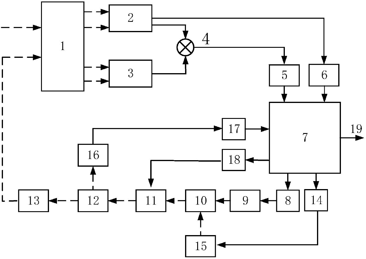
[0026] figure 1It is a structural block diagram of the optical phase-locked loop device based on the direct digital frequency synthesizer of the present invention. The solid line part is the connection of the electrical signal, and the dotted line is the connection of the optical signal. As can be seen from the figure, the present invention is based on an optical phase-locked loop device of a direct digital frequency synthesizer, comprising a 90-degree optical bridge 1, a first balanced detector 2, a second balanced detector 3, a mixer 4, a first mode Digital converter 5, serial-to-parallel conversion chip 6, FPGA7, DDS8, microwave amplifier 9, optical intensity modulator 10, fiber grating filter 11, fiber beam splitter 12, fiber amplifier 13, first digital-to-analog conve...
PUM
 Abstract
Description
Claims
Application Information