
3D printing and manufacturing method for surface microstructure of friction pair

A production method and 3D printing technology, applied in the direction of additive manufacturing, process efficiency improvement, additive processing, etc., can solve the problems of insignificant friction reduction effect and high production cost, and achieve the effect of wide application range and high production efficiency

Active Publication Date: 2018-04-20
TAIYUAN UNIV OF TECH
View PDF8 Cites 8 Cited by
  • Summary
  • Abstract
  • Description
  • Claims
  • Application Information

AI Technical Summary

Problems solved by technology

Analyzing the existing technology, the method of reducing friction and reducing wear by improving the precision of the contact surface will be limited by production conditions and machining accuracy, and the higher the machining accuracy, the higher the production cost, and the friction reduction effect is not obvious

Method used


Image

  • 3D printing and manufacturing method for surface microstructure of friction pair
  • 3D printing and manufacturing method for surface microstructure of friction pair
  • 3D printing and manufacturing method for surface microstructure of friction pair

Examples


Embodiment 1

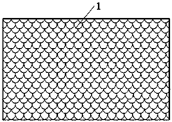
[0028] The 3D printing method of implementing the micro-texture on the surface of the friction pair is applied to the vane of the vane pump or motor. The shape of the micro-texture is fish scale, see the attached figure 1 , 1 is the blade raw material plate with fish scale texture vane pump or motor, the surface of the blade is covered with fish scale micro texture, the depth is 0.04mm, the width (laser beam spot diameter) is 0.2mm, and the distance between the two textures is 1.5mm. Use a CNC grinder to treat the surface of the friction pair, clean the oxide and rust on the surface of the raw material plate of the blade, and make the surface of the raw material plate of the blade smooth and bright; use the computer 3D CAD software to make the scale micro-texture required on the surface of the raw material plate of the blade. Draw to obtain the three-dimensional model of the fish scale micro-texture, and then use a series of small triangle planes to approximate the irregular s...

Embodiment 2

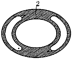
[0030] The 3D printing method of implementing the micro-texture on the surface of the friction pair is applied to the valve plate 2. The shape of the micro-texture is cylindrical, see the attached figure 2 , the contact surface between the valve plate and the cylinder body is covered with cylindrical micro-textures, the depth is 0.02mm, and the area is 0.1mm 2 , occupying an area ratio of 15%. The cylindrical micro-texture on the surface of the valve plate stores a certain amount of oil to increase the thickness of the oil film and increase the supporting force of the oil film, thereby reducing friction and wear. The manufacturing method of the cylindrical micro-texture on the surface of the required friction pair Same as Example 1.

Embodiment 3

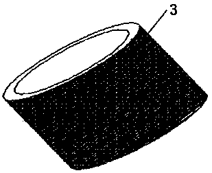
[0032] The 3D printing method of implementing the micro-texture on the surface of the friction pair is applied to the contact surface between the inner and outer ring of the roller (ball) bearing and the roller (ball). The shape of the micro-texture is rhombus, see the attached image 3 And attached Figure 4 , 3 is the inner ring of the roller bearing, and 4 is the outer ring of the roller bearing. The inner ring of the roller bearing and the roller form a friction pair. 2 has an area of ​​0.2 mm2 , the depth is 0.02mm, and the manufacturing method of the rhombic micro-texture on the surface of the desired friction pair is the same as that in Example 1.

[0033] In summary, this method provides a 3D printing manufacturing method for the surface micro-texture of the friction pair, which overcomes some deficiencies and limitations of the friction pair in the background technology, improves the lubrication performance of the friction pair, and improves the friction The wear res...


PUM

PropertyMeasurementUnit
thicknessaaaaaaaaaa
depthaaaaaaaaaa
widthaaaaaaaaaa

Abstract

The invention provides a 3D printing and manufacturing method for a surface microstructure of a friction pair. The method comprises the steps of treating the surface of the friction pair of a elementto be machined by using a computer numerical control (CNC) grinding machine, and drawing a 3D model of the surface microstructure of the required friction pair through computer 3D CAD software; makingapproximate treatment to the 3D model from a small triangle to obtain an approximate model; dividing the approximate model into sheets of a series of thicknesses in the height direction, and extracting and processing contour information to generate CNC programs; then, inputting the CNC programs into a manipulator control device, and fixing the element to be machined to a workbench through a clamping device; and applying metal powder to the surface of the element to be machined for a certain thickness, and driving a laser device by the manipulator control device for performing laser sinteringfor the element to be machined according to a predetermined path, so that the surface microstructure of the required friction pair is formed, and the abrasion resistance and friction resistance of thefriction surface are improved effectively.

Description

technical field [0001] The invention relates to a production method for friction reduction and anti-wear of a friction surface, in particular to a 3D printing production method for micro-texture on the surface of a friction pair. Background technique [0002] Hydraulic transmission technology is widely used in the industrial field. Vane pumps and vane motors are also frequently used hydraulic components. Among them, the friction pair between the vane and the rotor, as well as the friction pair of the valve plate of the plunger pump and the cylinder block are all hydraulic components. The key friction pair of the device is the most prone to wear and failure. Its quality directly affects the noise, flow and volumetric efficiency of hydraulic pumps and hydraulic motors. Under heavy load conditions, the friction pair formed by the inner and outer rings of the roller bearing and the roller is also a friction pair that is easy to wear and damage, and its quality also directly affe...

Claims


Application Information

Patent Timeline
Patent Type & Authority Applications(China)
IPC IPC(8): B22F3/105B33Y10/00B22F5/00
CPCB22F5/00B33Y10/00B22F10/00B22F10/66B22F12/41B22F12/63B22F10/28B22F10/36B22F12/10B22F10/68Y02P10/25
Inventor 权龙秦涛谢学斌王波
Owner TAIYUAN UNIV OF TECH
Learn More