Preheating method for fuel gas of reforming heating furnace and reforming device

A technology of reforming device and fuel gas, which is applied in the field of reforming device and fuel gas preheating of reforming furnace, which can solve the problems of direct combustion pollution emission, inability to realize fuel gas fine treatment, low temperature flue gas dew point corrosion, etc. , to achieve the effect of solving the problem of excessive sulfur dioxide, solving the problem of dew point corrosion, and reducing the amount of flue gas

Pending Publication Date: 2018-04-20
上海浩用工业炉有限公司
View PDF0 Cites 4 Cited by
  • Summary
  • Abstract
  • Description
  • Claims
  • Application Information

AI Technical Summary

Problems solved by technology

Reducing the exhaust gas temperature of the heating furnace and recovering the waste heat of the flue gas are effective solutions to improve the thermal efficiency of the heating furnace, but the low-temperature flue gas dew point corrosion problem is the key problem restricting this solution
In addition, the fuel gas of the reformer comes from the fuel gas pipeline network of the refinery. Although the fuel gas in the pipeline network has been roughly treated, it is still difficult to meet the latest environmental protection standard

Method used


Image

  • Preheating method for fuel gas of reforming heating furnace and reforming device
  • Preheating method for fuel gas of reforming heating furnace and reforming device
  • Preheating method for fuel gas of reforming heating furnace and reforming device

Examples


Embodiment 1

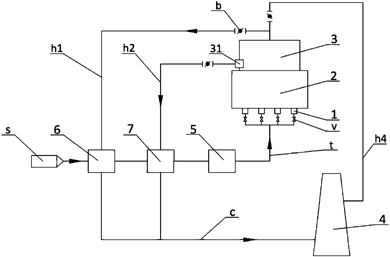
[0029] Such as figure 1 As shown, two stages of fuel gas preheating units are arranged on the fuel gas passage t, which are the first preheater 6 and the second preheater 7 respectively. The flue gas drawn from the top of the convection section 3 passes through the first hot flue h1 into the first preheater 6, and performs a heat exchange with the fuel gas from the fuel gas pipe network s; the position before the flue gas in the convection section 3 enters the waste heat boiler A flue gas outlet 31 in the convection section is provided, and the flue gas drawn from it passes through the second hot flue h2 into the second preheater 7 for secondary heat exchange with the fuel gas. A baffle b is set on the first hot flue h1 to adjust the amount of flue gas passing into the first preheater 6; a similar baffle can also be set on the second hot flue h2 to control the amount of flue gas flowing into the second Flue gas volume of preheater 7. The preheated fuel gas is passed into the...

Embodiment 2

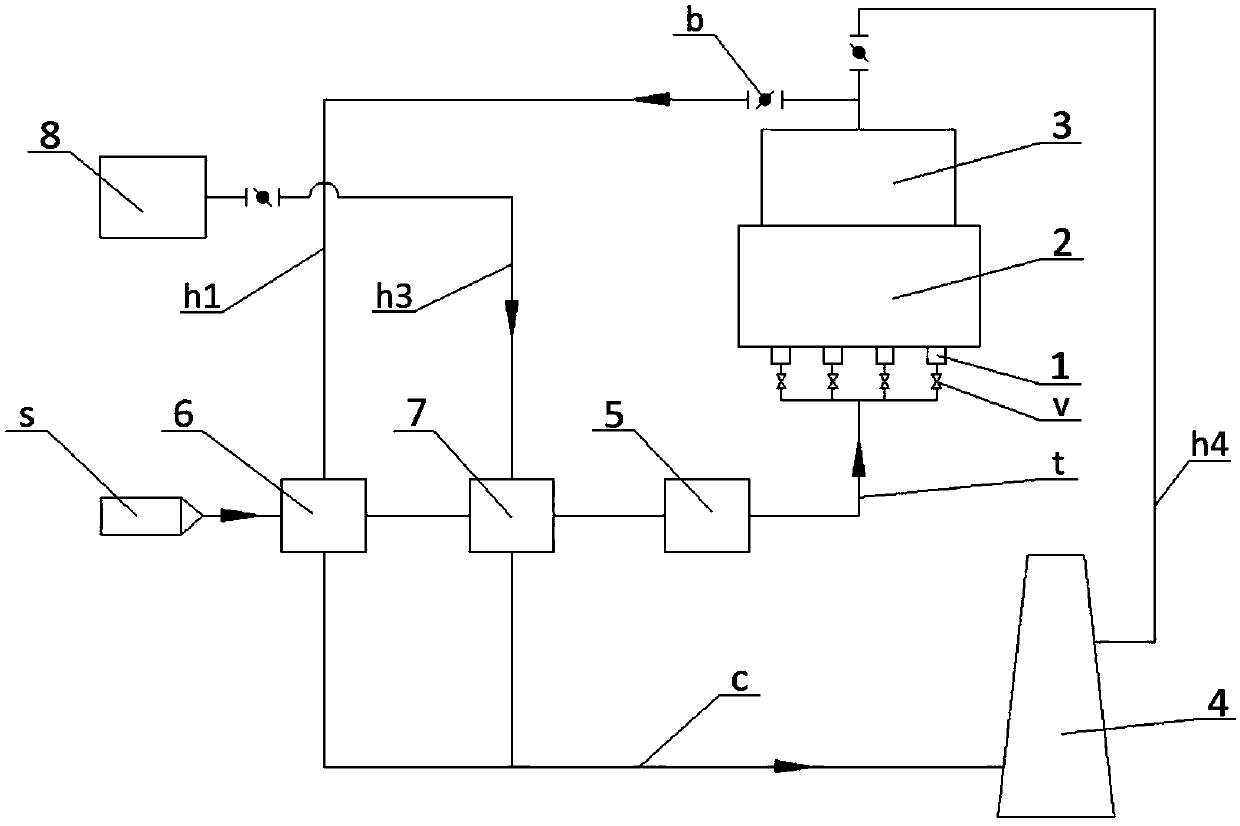
[0031] The difference between the fuel gas preheating method of the reforming furnace in this embodiment and that in Embodiment 1 is that the secondary preheating does not use the waste heat of the high-temperature flue gas in the reforming furnace located at the rear end, but uses the reforming furnace at the rear end The high-temperature flue gas provided by other high-temperature flue gas sources and the fuel gas exchange heat to heat the fuel gas.

[0032] Such as figure 2 As shown, the two-stage fuel gas preheating units installed on the fuel gas passage t are also the first preheater 6 and the second preheater 7, both of which use the waste heat of the flue gas to exchange heat with the fuel gas to achieve fuel gas preheating. The flue gas drawn from the top of the convection section 3 passes through the first hot flue h1 into the first preheater 6, and performs a heat exchange with the fuel gas from the fuel gas pipe network s; other high-temperature flue gas sources 8...

Embodiment 3

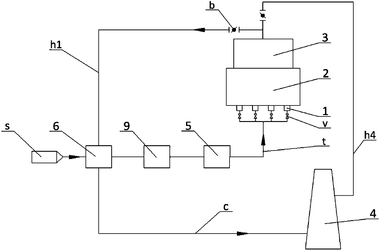
[0034]The difference between the fuel gas preheating method of the reforming furnace in this embodiment and the previous embodiments is that the secondary preheating does not use high-temperature flue gas waste heat, but uses electric heating to directly heat the fuel gas.

[0035] Such as image 3 As shown, a two-stage fuel gas preheating unit is also set on the fuel gas passage t, wherein the primary preheating device is the first preheater 6, and the flue gas is drawn from the top of the convection section 3 to pass through the first hot flue h1 Pass into the first preheater 6 to exchange heat with the fuel gas from the fuel gas pipe network s; the secondary fuel gas preheating unit is an electric heater 9, which will exchange heat with the flue gas in the first preheater 6 The output fuel gas is passed into the electric heater 9 for secondary preheating, the heated fuel gas is passed into the fuel gas finishing treatment unit 5 for finishing treatment, and the processed fu...


PUM


Abstract

The embodiment of the invention provides a preheating method for fuel gas of a reforming heating furnace. The method comprises the steps that before the fuel gas enters the reforming heating furnace,primary preheating and secondary preheating are carried out; in the primary preheating process, the fuel gas and flue gas guided out are subjected to heat exchange in a first preheater; then the fuelgas is introduced into a secondary fuel gas preheating unit for secondary preheating; and the fuel gas subjected to secondary preheating is introduced into a fuel gas fine treatment unit for fine treatment and then is introduced into a combustor for combustion. The method has the advantages that the high-temperature flue gas entering the convection section is used for preheating the fuel gas, theamount of steam produced by the fuel gas can be decreased, and the energy utilization efficiency can be improved; and meanwhile, the fuel gas is preheated to the temperature meeting the finish treatment, and therefore the problem that sulfuric acid dew point corrosion occurs after the heat efficiency of the heating furnace is improved can be solved, the problem that the content of sulfur dioxide exceeds the standard when the fuel gas coarse desulfurization system fluctuates can be solved, and the emission concentration of nitric oxide can be further decreased. The embodiment of the invention further provides a reforming device based on the preheating method for the fuel gas of the reforming heating furnace.

Description

technical field [0001] The invention belongs to the technical field of petrochemical reforming, in particular to a fuel gas preheating method of a reforming heating furnace. The present invention also provides a reformer using the above fuel gas preheating method. Background technique [0002] The reformer is an important device in petrochemical plants, mainly producing high-quality gasoline and by-product hydrogen. The reforming reaction is a strong endothermic reaction, and it is necessary to use multiple heating furnaces to provide heat for the reforming reaction and product separation. Among them, the reforming reactor feed heating furnace is generally called a reforming furnace. The typical design of the reforming furnace is to combine four heating furnaces into a large portal heating furnace, with four radiation chambers separated by a fire wall or an air wall in the middle to avoid temperature interference. The furnace tubes of each radiation chamber are connected ...

Claims


Application Information

Patent Timeline
IPC IPC(8): F23D14/66F23D14/68B01D53/50B01D53/56C10G35/02
CPCB01D53/50B01D53/56F23D14/66F23D14/68C10G35/02Y02E20/34
Inventor 闫广豪张明会罗洋
Owner 上海浩用工业炉有限公司
Why Eureka
Try Eureka