Gas liquefaction system

A gas and liquefied gas technology, applied in the field of liquefaction, can solve problems such as safety, cost, system efficiency reduction, and complex process flow

Pending Publication Date: 2018-04-20
TECHNICAL INST OF PHYSICS & CHEMISTRY - CHINESE ACAD OF SCI
View PDF5 Cites 12 Cited by
  • Summary
  • Abstract
  • Description
  • Claims
  • Application Information

AI Technical Summary

Problems solved by technology

[0006] For this traditional process, one method is that the gas-liquid two-phase fluid directly enters the liquid storage tank after throttling, and after the gas is reheated, the pressure is raised by a hydrogen compressor for recycling. This process is complicated, and hydrogen is flammable. Explos

Method used


Image

  • Gas liquefaction system
  • Gas liquefaction system
  • Gas liquefaction system

Examples


Embodiment Construction

[0022] In order to make the purpose, technical solution and advantages of the present invention clearer, the present invention will be further described in detail below in conjunction with the accompanying drawings and embodiments. It should be understood that the specific embodiments described here are only used to explain the present invention, not to limit the present invention.

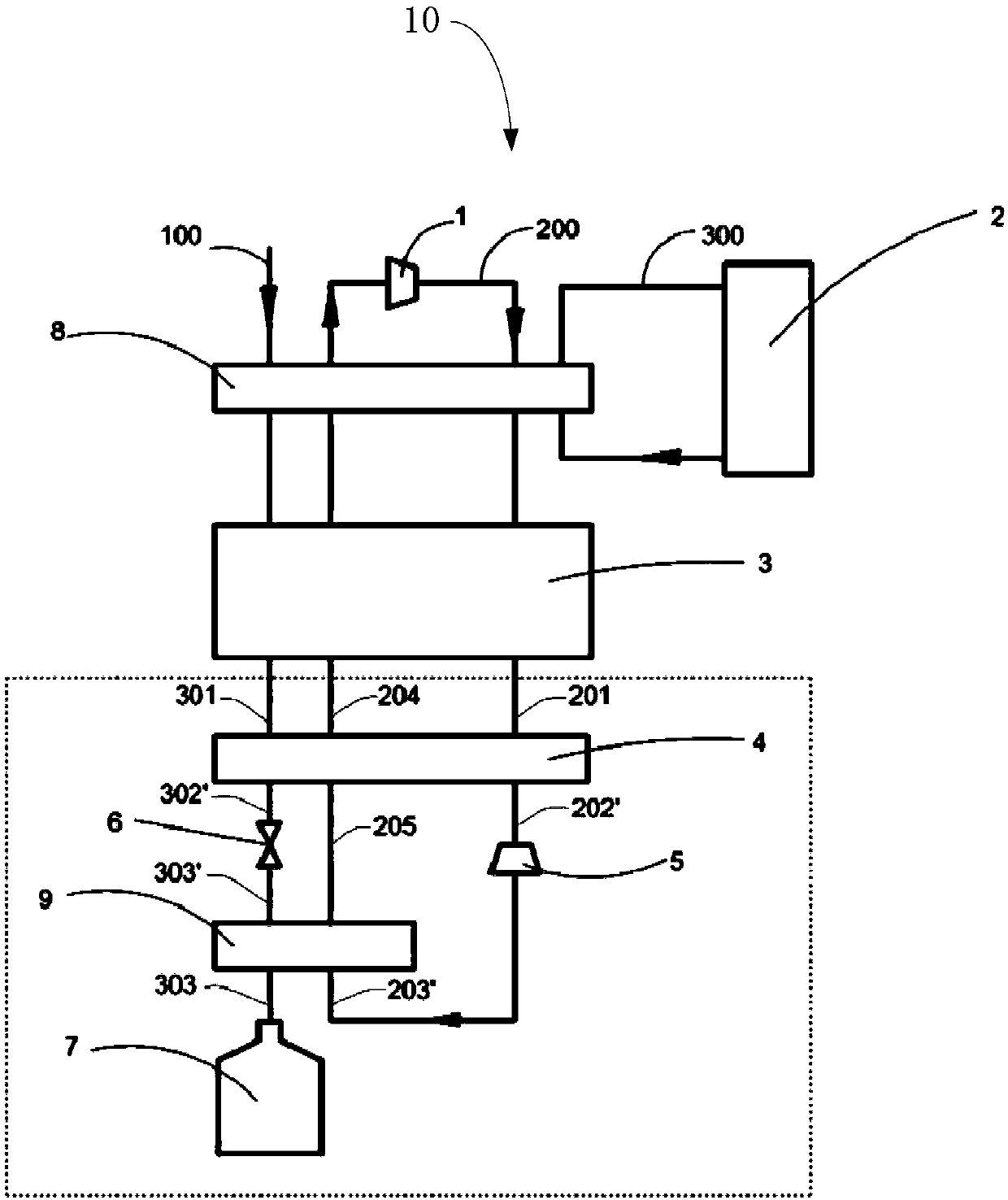
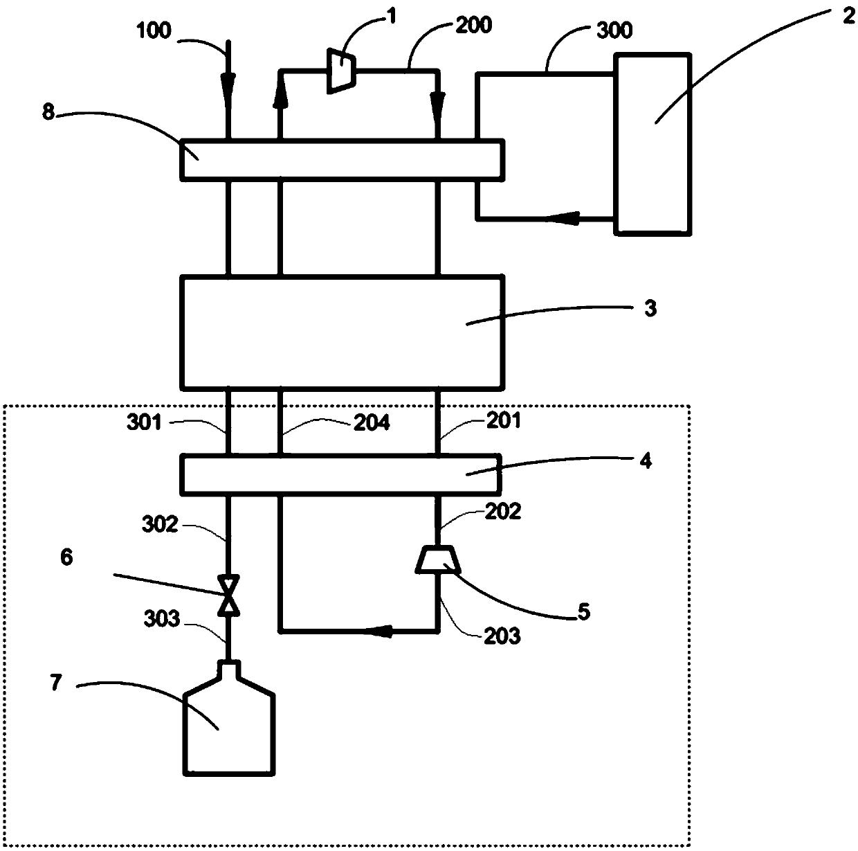
[0023] Such as figure 2 As shown, a gas liquefaction system 10 of an embodiment includes a compressor unit 1, a precooling heat exchanger 8, a multi-stage intermediate turbine precooling unit 3, a first heat exchanger 4, a final turbo expander 5, a second Two heat exchangers 9, a throttle valve 6 and a cryogenic liquid storage tank 7.

[0024] The outlet of the compressor unit 1 is connected to the high-pressure side refrigerant inlet of the pre-cooling heat exchanger 8, and the high-pressure side refrigerant outlet of the pre-cooling heat exchanger 8 is connected to the high-pressure side refri...


PUM


Abstract

A gas liquefaction system comprises a compressor unit, a precooling heat exchanger, a multistage intermediate turbine precooling unit, a first heat exchanger, a final-stage turbine expander, a secondheat exchanger, a throttle valve and a cryogenic liquid storage tank. The second heat exchanger is arranged between the throttle valve and the cryogenic liquid storage tank. The gas liquefaction system comprises a to-be-liquefied gas circuit, a refrigeration working medium circulating process and a precooling working medium circulating loop. According to the gas liquefaction system, under the samesystem power consumption, the final-stage turbine expander expands under the high temperature by changing the liquefaction process form of the cryogenic end so as to obtain the greater cooling capacity; compared with a traditional helium refrigeration hydrogen liquefaction system, a stage of second heat exchanger is further additionally arranged after throttling of the throttle valve so that thedryness of the liquefied gas can be further decreased to zero, full liquid phase running of an outlet pipeline of the second heat exchanger is ensured, the safe effect is achieved, and the equipment cost is saved; and the lowest temperature of the whole gas liquefaction system is improved, improving of the system efficiency is facilitated, and energy sources are saved.

Description

technical field [0001] The invention relates to the technical field of liquefaction, in particular to a gas liquefaction system. Background technique [0002] As the fossil fuels that meet the current world energy demand are almost exhausted, and their combustion products will pollute the environment, the search for new energy has become a major issue that has attracted worldwide attention. Hydrogen is rich in resources and has various sources. As a secondary energy source, it has the advantages of high combustion calorific value, clean and environmentally friendly, storable, and renewable. And hydrogen energy can meet the requirements of resources, environment and sustainable development at the same time, so it is called the future energy of mankind. [0003] Hydrogen gas is usually an equilibrium mixture of ortho and para hydrogen. The equilibrium concentration of hydrogen varies significantly with temperature. When the temperature is lowered, orthohydrogen with a high-...

Claims


Application Information

Patent Timeline
IPC IPC(8): F25J1/02
CPCF25J1/0219F25J1/0279F25J2215/10F25J1/001F25J1/005F25J1/0052F25J1/0065F25J1/0072F25J2240/40F25J2290/34
Inventor 吕翠伍继浩龚领会李青
Owner TECHNICAL INST OF PHYSICS & CHEMISTRY - CHINESE ACAD OF SCI
Why Eureka
Try Eureka