Line-contact sliding-friction vibration noise test bench

A sliding friction, vibration and noise technology, used in vibration testing, machine/structural component testing, measuring devices, etc., can solve the problems of no testing device, high sound insulation cost, and difficulty in eliminating noise, and achieve precise characteristics and effects. Factors, convenient disassembly and replacement of specimens, and the effect of reducing test costs

Inactive Publication Date: 2018-05-04
NORTHWESTERN POLYTECHNICAL UNIV
View PDF5 Cites 6 Cited by
  • Summary
  • Abstract
  • Description
  • Claims
  • Application Information

AI Technical Summary

Problems solved by technology

[0003] In the existing technology, the contact forms for the research of sliding friction vibration noise are mostly point contact and surface contact, such as the patent No. 201210189588.0 "A test and analysis method for friction noise and its test device" and the document "D.W.Wang, J.L. Mo, et al. Noise performance improvements and tribological consequences of a pad-on-disc system through groove-textured disc surface [J]. Tribology International, 2016, 102: 222-236 "disclosed test bench, can respectively complete the point contact The measurement and research of sliding friction noise in the form of surface contact, but for the sliding friction noise in the form of line contact, the above-mentioned test bench cannot be realized. Noise elimination or sound insulation device for friction noise, used to eliminate or reduce the interference of background noise during the test process, but no specific test device for generating friction noise is provided
From the existing patents and literatures, it can be seen that the research on friction noise is lack of experimental research on line contact sliding friction noise, and the background noise of noise test is difficult to eliminate or the cost of sound insulation is high.

Method used


Image

  • Line-contact sliding-friction vibration noise test bench
  • Line-contact sliding-friction vibration noise test bench
  • Line-contact sliding-friction vibration noise test bench

Examples


Embodiment Construction

[0021] The present invention will be further described below in conjunction with the accompanying drawings and embodiments, and the present invention includes but not limited to the following embodiments.

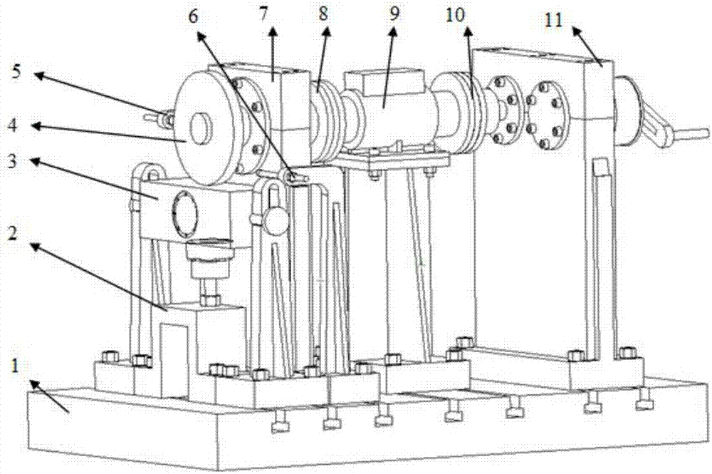
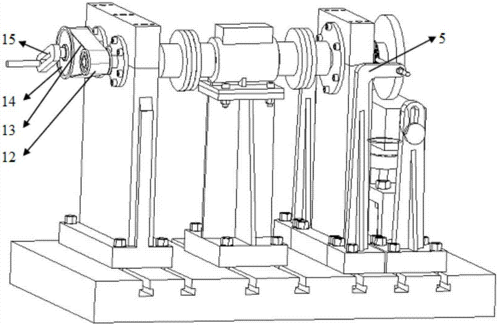
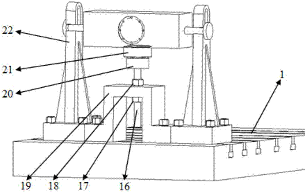
[0022] A line contact sliding friction vibration noise test bench in this embodiment mainly includes a basic platform 1, a loading assembly 2, a plane specimen 3, a cylindrical specimen 4, a velocity sensor 5, an acoustic sensor 6, a support assembly 7, a front coupling Shaft device 8, torque sensor 9, rear coupling 10, timing belt support assembly 11, small pulley 12, timing belt 13, large pulley 14, driving rocker arm 15. Such as figure 1 and figure 2As shown, the loading assembly 2, supporting assembly 7, and synchronous belt supporting assembly 11 are respectively installed on the foundation platform 1 through T-slot bolts; the plane specimen 3 is installed on the loading assembly 2 through the U-shaped groove; the cylindrical specimen 4 is installed through the shaft...


PUM


Abstract

The invention provides a line-contact sliding-friction vibration noise test bench. The test bench adopts the sliding motion form of contact between plane specimen and cylinder specimen line, and line-contact sliding-friction vibration noise test can be realized; specimen disassembly and replacement can be facilitated by adopting the design of cantilever installation of the cylinder specimen and replaceable parts and supports, external loads of different sizes and speeds are applied to the specimen through a loading component and a synchronous-belt support component, and the line-contact sliding-friction vibration noise test bench of specimen pairs with different surface roughness and different types of materials can be realized under different loads. By the adoption of a manual drive mode,problems about too many intermediate links of motor driven motion transmission and too much background noise needing sound-insulating treatment and the like are avoided, test cost is lowered, and characteristics and influencing factors of friction noise under the line-contact sliding motion form can be researched more accurately.

Description

technical field [0001] The invention belongs to the technical field of friction noise testing in mechanical engineering, in particular to a line contact sliding friction vibration noise test bench. Background technique [0002] With the development and progress of industry, the requirement of low noise in the working environment has become an important evaluation index of various mechanical products, and the impact of friction noise in industrial equipment and traffic equipment is particularly direct and obvious. It not only damages the hearing of the human ear, but also makes the sound fatigue of mechanical parts and reduces the service life. Vibration and noise caused by interface friction is a very complex physical phenomenon, which involves knowledge of various disciplines, including tribology, contact mechanics, dynamics, and acoustics. The research on frictional noise mostly relies on experimental means, and most of the research is on the sliding contact of surface-to...

Claims


Application Information

Patent Timeline
Patent Type & Authority Applications(China)
IPC IPC(8): G01M7/02
CPCG01M7/02
Inventor 刘更南咪咪刘岚焦阳
Owner NORTHWESTERN POLYTECHNICAL UNIV
Why Eureka
Try Eureka