
Electronic control differential mechanism in vector linkage with multi-wheel vehicle steering control mechanism

A technology of control mechanism and differential mechanism, which is applied in the direction of steering mechanism, fluid steering mechanism, steering rod, etc., and can solve the problem of not clearly displaying the output voltage of the generator

Inactive Publication Date: 2018-05-15
刘海鹏 +1
View PDF8 Cites 8 Cited by
  • Summary
  • Abstract
  • Description
  • Claims
  • Application Information

AI Technical Summary

Problems solved by technology

Among them, the differential lock starts and locks with the centrifugal slider is the most representative. In the patent search, several electronic differentials are seen. The documents of Shaanxi Institute of Technology and Dongfeng Research Institute are used as representative benchmarks. They are controlled by ECU centrally. The electronic speed control is mainly carried out by the electronic speed controller, and the independent drive of the distributed wheel hub motors is controlled. The calculation process is to first calculate the steering radius, and then calculate the differential speed target of each wheel drive. The output voltage of the machine is the control target, and its steering mechanism is also limited within the acute angle steering and the steering center of the frame cannot be moved

Method used


Image

  • Electronic control differential mechanism in vector linkage with multi-wheel vehicle steering control mechanism
  • Electronic control differential mechanism in vector linkage with multi-wheel vehicle steering control mechanism
  • Electronic control differential mechanism in vector linkage with multi-wheel vehicle steering control mechanism

Examples


Embodiment Construction

[0020] 1. The steering mechanism obtains the key control point bearing control vector drive voltage signal.

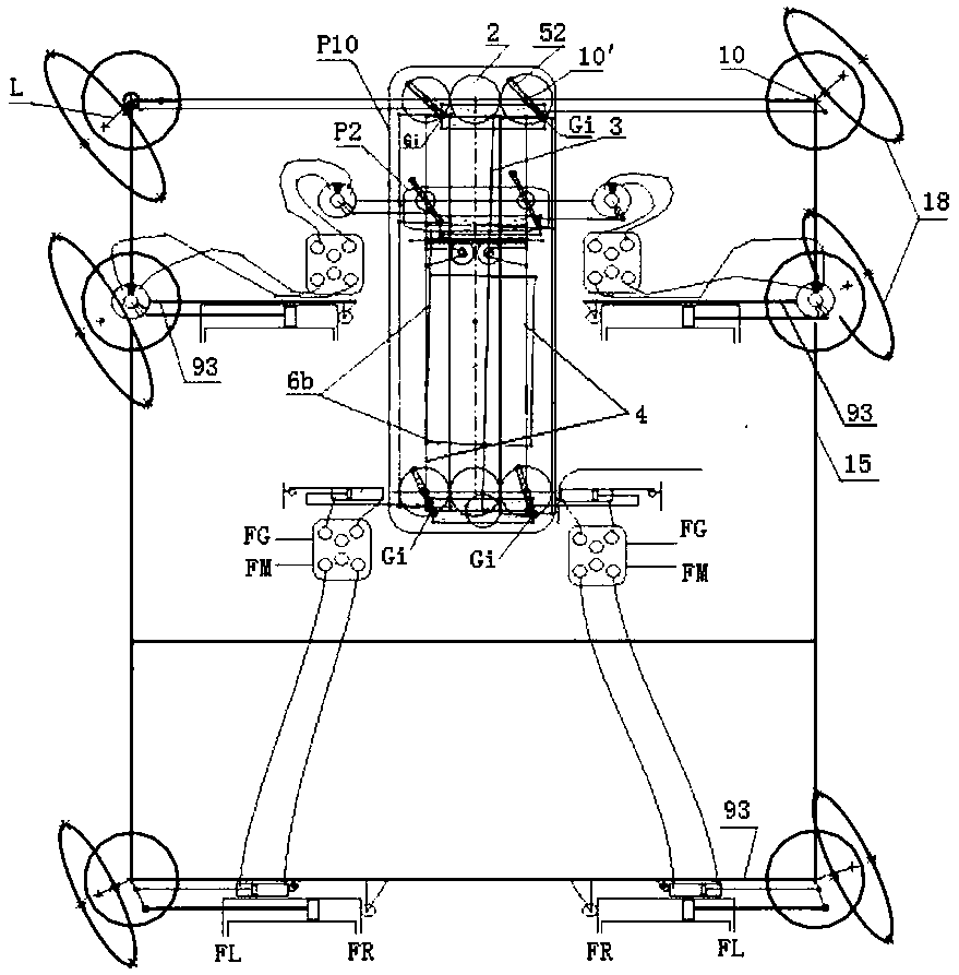
[0021] figure 1 It is a schematic diagram of the overall structure of the model steering mechanism, which is the same as the application number 2017201709604.8. It provides the basis for obtaining the key control point bearing Gi, the specific principle has been made public and will not be repeated here.

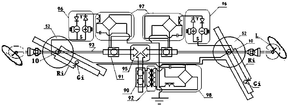
[0022] figure 2 The positions of the steering shaft (10) and auxiliary steering shaft (10') in figure 1 From the area of ​​the second axis auxiliary steering shaft 10' shown in the vector control arm sliding pole shoe controller P2 in the model controller P10, it mainly indicates the key control point bearing Gi controls the sliding potentiometer output terminal pole shoe to obtain the vector control difference The target voltage U0i of the speed control, because there is no driving half shaft in the model controller P10, so the driving half shaft 93 is extended ...


PUM


Abstract

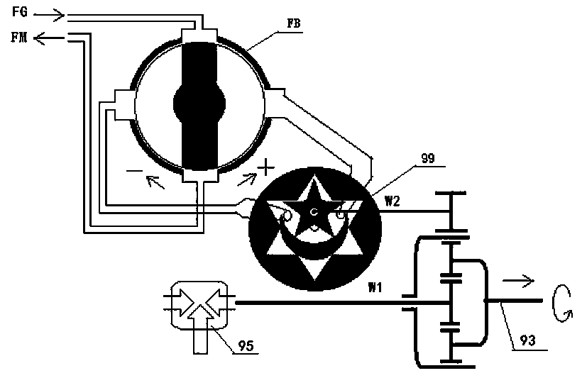
The invention relates to an electronic control differential mechanism in vector linkage with a multi-wheel vehicle steering control mechanism. The electronic control differential mechanism is built onthe basis that a multistage universal steering control mechanism obtains a key operating point bearing and makes steering shaft swing arms become vector control arms; the lengths of the vector control arms are in direct proportion to corresponding wheel speeds; the motor voltage is in direct proportion to the angular speed; a main shaft motor or quadrangle speed measurement motor combination uniformly supplies electricity to an alternating-current transformer or slide potentiometer input end, corresponding to the steering vector control arm length synchronous connection control output end slide pole shoe position, the output target voltage and voltage generated by speed measurement motors installed on all wheel drive haft shafts are compared through a double branch voltage balance comparison servo circuit assembly, generated voltage unbalance diode electric signals feed back a servo device controlling one of six electronically controlled differential or speed regulating modes selectedby all axial directions, and the drive half shaft angular speed is increased or decreased to reach the voltage balance state.

Description

technical field [0001] The invention relates to an electronic control differential mechanism of a multi-wheel vehicle universal steering mechanical control mechanism, which belongs to the technical field of wheel steering control of non-track multi-wheel vehicles for land use. Background technique [0002] At present, in the steering technology of multi-wheel vehicles at home and abroad, the side wheel steering is mainly based on trapezoidal transmission compensation. In rear wheel steering, trapezoidal transmission compensation is common, and there is also microcomputer numerical control power steering; The current advanced technology in all-wheel steering is the use of microcomputer-controlled wheel power steering technology, that is, steering-by-wire technology, and the use of two-way hydraulic power steering in the introduction of foreign heavy truck technology. In the steering differential control technology, it mainly relies on the differential and the differential loc...

Claims


Application Information

Patent Timeline
Patent Type & Authority Applications(China)
IPC IPC(8): B62D5/06B62D5/09B60K17/16B62D7/14B60K17/348G06F17/50
CPCB60K17/165B60K17/348B62D5/06B62D5/09B62D7/144G06F30/15G06F30/20
Inventor 刘海鹏
Owner 刘海鹏
Learn More