Eureka AIR delivers breakthrough ideas for toughest innovation challenges, trusted by R&D personnel around the world.

Sludge power generation and incineration treatment system

A treatment system and sludge power generation technology, applied in biomass post-processing, incinerators, combustion methods, etc., can solve the problems of affecting air quality, difficult to catch fire, occupying space, etc.

Pending Publication Date: 2018-05-15
天津远新环保科技有限公司
View PDF9 Cites 1 Cited by
  • Summary
  • Abstract
  • Description
  • Claims
  • Application Information

AI Technical Summary

Problems solved by technology

Most of the existing sludge incinerators use a fluidized bed incinerator to incinerate the sludge and then discharge it. However, the sludge will generate a large amount of methane during fermentation in the fermentation tank. If it is directly discharged into the air, it will not only affect the air quality , and may cause explosion hazards
Now there is also the recovery of biogas for power generation or use in kitchens, but the existing biogas reuse systems are generally equipped with sludge fermentation tanks and biogas tanks, and the biogas generated in the sludge fermentation tanks is introduced into the biogas tank for storage. , this kind of system not only takes up space but also the biogas will contain a lot of impurities such as carbon and sulfur without purification treatment, which will not only affect the efficiency of power generation when it is reused, but also if it is used for kitchen fire, it may be difficult to start a fire or The fire was put out halfway, causing an accident

Method used


Image

  • Sludge power generation and incineration treatment system

Examples


Embodiment Construction

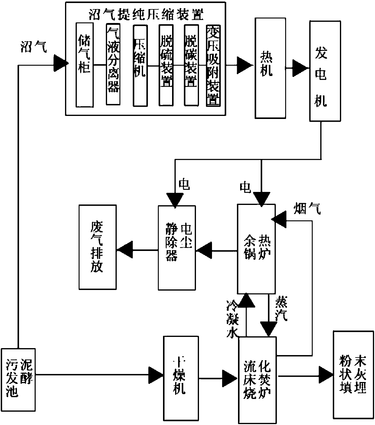
[0015] A sludge power generation incineration treatment system, which includes a sludge fermentation tank, a biogas purification and compression device, a heat engine, a generator, a dryer, an incinerator, and a waste heat boiler. The sludge fermentation tank includes a fermentation tank sludge inlet, a fermentation tank The sludge outlet and the biogas outlet of the fermentation tank. The biogas purification and compression device includes a gas storage cabinet, a gas-liquid separator, a compressor, a desulfurization device, a decarbonization device and a pressure swing adsorption device connected to each other in sequence. The dryer is equipped with Dryer sludge inlet, dryer sludge outlet, steam inlet and condensed water outlet, the incinerator includes incinerator sludge inlet, air inlet, slagging outlet and incinerator smoke outlet. The waste heat boiler is provided with a water inlet, a steam outlet, a waste heat flue gas inlet and a boiler exhaust port;

[0016] The slud...


PUM


Abstract

The invention relates to the field of sludge treatment equipment, in particular to a sludge power generation and incineration treatment system. The sludge power generation and incineration treatment system comprises a sludge fermentation pool, a marsh gas purifying and compressing device, a heat machine, an electric generator, a drying machine, an incineration furnace and an afterheat boiler, wherein the sludge fermentation pool comprises a fermentation pool sludge inlet, a fermentation pool sludge outlet and a fermentation pool marsh gas outlet; the marsh gas purifying and compressing devicecomprises a gas storage cabinet, a gas and liquid separator, a compressor, a desulfurizing device, a decarbonizing device and a pressure swing adsorption device which are connected mutually and sequentially; the drying machine is provided with a drying machine sludge feeding opening, a drying machine sludge discharging opening, a steam inlet and a condensed water inlet; the incineration furnace comprises an incineration furnace sludge feeding opening, an air inlet, a slag discharging opening and an incineration furnace smoke discharging opening; the afterheat boiler is provided with a water inlet, a steam outlet, an afterheat flue gas inlet and a boiler smoke discharging opening. The device provided by the invention is high in marsh gas utilization rate and marsh gas purity, safe, and reliable.

Description

technical field [0001] The invention relates to the field of sludge treatment equipment, in particular to a sludge power generation incineration treatment system. Background technique [0002] Sewage treatment plants will produce sludge in the process of sewage treatment, and the sludge needs to be incinerated after being dehydrated by dehydration equipment, and discharged after meeting the requirements of reduction and harmlessness. Most of the existing sludge incinerators use a fluidized bed incinerator to incinerate the sludge and then discharge it. However, the sludge will generate a large amount of methane during fermentation in the fermentation tank. If it is directly discharged into the air, it will not only affect the air quality , and may cause hazards such as explosion. Now there is also the recovery of biogas for power generation or use in kitchens, but the existing biogas reuse systems are generally equipped with sludge fermentation tanks and biogas tanks, and t...

Claims


Application Information

Patent Timeline
Patent Type & Authority Applications(China)
IPC IPC(8): C12M1/107F23G7/00F23J15/02
CPCF23G7/001F23J15/022C12M21/04C12M23/36C12M43/04C12M43/08C12M47/18F23G2206/20F23J2217/102Y02E20/12Y02E50/30
Inventor 王学科马竞男穆童谢迎辉芦珊珊刘静伟吴建光张永旺
Owner 天津远新环保科技有限公司
Why Eureka
Eureka Blog
Learn More