Control device and method for power factor correction converter

A power factor correction and control device technology, which is applied in the direction of output power conversion devices, high-efficiency power electronic conversion, electrical components, etc., can solve the power switch tube turn-on loss, power switch tube drive loss, difficult to meet high efficiency requirements, etc. question

Active Publication Date: 2018-05-25
DELTA ELECTRONICS DONGGUAN
View PDF10 Cites 7 Cited by
  • Summary
  • Abstract
  • Description
  • Claims
  • Application Information

AI Technical Summary

Problems solved by technology

The controller of the power factor correction converter (PFC) of the existing switching power supply technology generally adopts the continuous current mode (CCM) control mode, but because the inductor current is continuous, the power switch tube has a turn-on loss, and the efficiency requirement is high under light load or standby It is difficult to meet the requirements of the application
Therefore, under light load and standby conditions, the discontinuous current mode (DCM) control method is often used, but the existing DCM control strategies will increase the switching frequency as the PFC load power decreases, such as voltage follower control and critical current mode. (CrCM) control, etc., resulting in large drive loss of the power switch tube under light load and standby conditions, and it is difficult to meet the high efficiency requirements

Method used


Image

  • Control device and method for power factor correction converter
  • Control device and method for power factor correction converter
  • Control device and method for power factor correction converter

Examples


Embodiment Construction

[0073] Herein, the detailed content and technical description of the present invention will be further described with a preferred embodiment, but it should not be construed as a limitation to the implementation of the present invention.

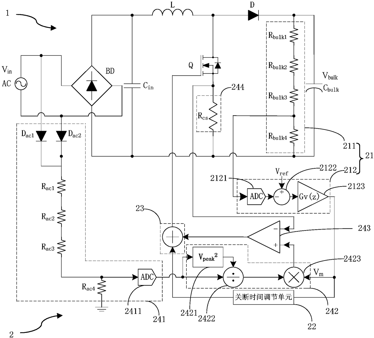
[0074] Please refer to figure 1 , figure 1 It is a structural schematic diagram of a control device for a power factor correction converter of the present invention. Such as figure 1 As shown, the power factor correction converter 1 includes a rectifier bridge BD, an input filter capacitor C in, boost inductor L, power switch tube Q, diode D and output filter capacitor C bulk , the power factor correction converter 1 obtains the AC input voltage V from the AC input terminal in , the DC output voltage V is converted by the power factor correction converter bulk . The control device 2 includes a PID control unit 21, an off-time adjustment unit 22, an on-time adjustment unit 23, and a control unit 24; the PID control unit 21 outputs a cont...


PUM


Abstract

The invention discloses a control device and method for a power factor correction converter. The control device comprises a PID control unit, an off-time adjustment unit, an on-time adjustment unit and a switching frequency control unit, wherein the PID control unit is used for outputting a control signal Vm based on an output voltage of the power factor correction converter, the off-time adjustment unit is used for outputting an off-time adjustment signal of a power switch tube of the power factor correction converter based on the PID control signal Vm, the on-time adjustment unit is used foroutputting an on-time adjustment signal based on an input voltage Vin of the power factor correction converter, the control signal Vm and a power switch tube current sampling signal, and the switching frequency control unit is used for adjusting the switching frequency of the power switch tube based on the off-time adjustment signal and the on-time adjustment signal.

Description

technical field [0001] The invention relates to a control device and a control method for a power factor correction converter, in particular to a control device and a control method capable of reducing the loss of a power switch tube of the power factor correction converter. Background technique [0002] Switching power supplies have the advantages of small size, high efficiency, and high power density, and have been widely used in power systems, industries, transportation, and households. The resulting problems such as lower input power factor and harmonic pollution on the grid side are also becoming more and more serious. At the same time, with the development of green energy, more and more attention has been paid to the energy consumption of power supplies. As the power source of electrical equipment, the working efficiency of power supplies will directly affect the energy consumption of electrical equipment. The controller of the power factor correction converter (PFC) ...

Claims


Application Information

Patent Timeline
Patent Type & Authority Applications(China)
IPC IPC(8): H02M1/42
CPCH02M1/4208H02M1/0054Y02B70/10
Inventor 陈洲
Owner DELTA ELECTRONICS DONGGUAN
Why Eureka
Try Eureka