
Target control method for heating power generation system

A technology of power generation system and control method, which is applied in the direction of heating system, steam centralized heating system, heating method, etc., can solve the problems of unadjustable electric power, loss, and economic loss, etc., so as to keep the heating load constant and improve Stability, increased flexibility effects

Inactive Publication Date: 2018-06-05
NORTHEAST DIANLI UNIVERSITY
View PDF6 Cites 9 Cited by
  • Summary
  • Abstract
  • Description
  • Claims
  • Application Information

AI Technical Summary

Problems solved by technology

[0008] Third, once the unit enters the low vacuum (high back pressure) circulating water heating operation mode of the condenser, the electric power cannot be adjusted, which reduces the frequency modulation unit of the power grid, which is not conducive to the safe operation of the power grid
[0009] (3) The secondary heating network heater often adopts a large heat transfer end difference (10-20°C), which leads to an increase in the temperature of the heat source water supply, which is much higher than the normal exhaust temperature range of the steam turbine;
[0010] (4) No one has proposed a heat supply transformation plan for condenser circulating water for larger steam turbines (600MW, 1000MW, 1200MW, 1300MW). Working conditions, once a safety problem occurs, great economic losses will occur;
[0011] (5) No one has proposed a comprehensive optimization target control method for heating and power generation systems including heat sources, heat networks and heat users;
[0012] (6) The heating distance of the heating network is short. On the one hand, many heating heat users far away from thermal power plants cannot use the residual heat. On the other hand, many thermal power plants cannot realize their energy-saving potential due to the lack of heat users nearby.

Method used


Image

  • Target control method for heating power generation system
  • Target control method for heating power generation system
  • Target control method for heating power generation system

Examples


Embodiment Construction

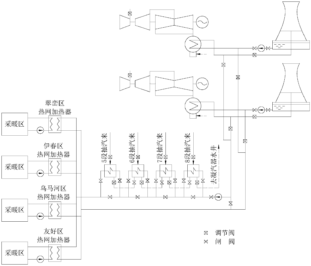
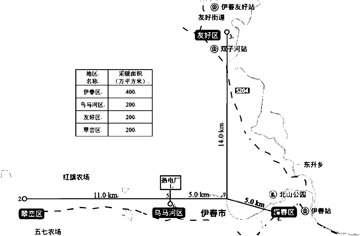
[0074] The present invention will be further described below in conjunction with the accompanying drawings and embodiments.

[0075] see Figure 1 to Figure 5 , the present embodiment takes the heating and heating system of the 2×C350-24.2 / 566 / 566 unit currently in service in Heilongjiang Yichun Thermal Power Plant as an example, and simulates the use process, method and effect of the technical solution of the present invention.

[0076] 1.1. Relevant standards and specifications

[0077] (1) Design Code for Heating, Ventilation and Air Conditioning of Civil Buildings (GB 50736-2012)

[0078] (2) Code for Design of Urban Heating Pipeline Network (CJJ34-2010)

[0079] (3) Technical Specifications for Energy Conservation of Urban Heating System (CJJ / T185-2012)

[0080] (4) Standards for Steam Surface Condensers (Eleventh Edition)

[0081] (5) Standard method for thermal calculation of boiler units

[0082] (6) Design guidelines for thermal insulation of equipment and pipeli...


PUM


Abstract

The invention provides a target control method for a heating power generation system. The target control method is suitable for various models and capacities of condensing steam turbines used for heating in all heating areas and safely realizes zero cold source heat loss in the heating of steam turbine condenser circulating water within the normal exhaust temperature range on the premise of not needing to reconstruct a steam turbine body, and the method has the beneficial effects that the effects of saving energy, saving the funds and shortening the construction period are realized for enterprises, the environment is protected, and the haze is reduced. During the heating of the circulating water, a unit can also participate in the peak shaving of a power grid and make the power grid operate more safely and stably. The heating radius of a hot water network exceeds the heating radius generated by means of the prior art and can reach 120-150 km. Meanwhile, a mathematic model is established to solve the operating parameter target values with the golden section algorithm, and the control with the highest energy supply efficiency as the target is achieved. The solution to the target values is more accurate, and scientific control measures are used to ensure the optimized, safe and reliable operation of the heating power generation system.

Description

technical field [0001] The invention belongs to the technical field of automatic control, and relates to a method for realizing target control of a steam turbine power generation system for heating and heating. technical background [0002] The heating involved in the present invention refers to building heating and heating, and the heat source comes from a steam turbine. [0003] There are two main ways to use condensing steam turbines to realize heating and power generation: one is to extract steam for heating, and the other is to supply heat by circulating water in the condenser, but either way has technical defects: [0004] (1) The method of extracting steam for heating is relatively common, and the main defect is that the exhaust steam must enter the steam turbine condenser, and the heat loss of the cold source must be discharged to nature, resulting in waste; [0005] (2) Condenser circulating water heating is an operation mode without heat loss from cold source, but...

Claims


Application Information

Patent Timeline
IPC IPC(8): F24D1/04F24D19/10F01D15/10F01K11/02
CPCF01D15/10F01K11/02F24D1/04F24D19/1003F24D2220/042Y02B30/00Y02P80/10
Inventor 张莹瑾陈奇成王林张炳文刘博伦韩为马杰杨萍
Owner NORTHEAST DIANLI UNIVERSITY
Learn More