Dual-frequency diffraction antenna capable of independently scanning beams

An antenna and beam technology, applied in the field of beam reconfigurable diffractive antennas, achieves the effects of low cost, fast electronically controlled beam scanning, and simple structural design

Inactive Publication Date: 2018-06-08
ZHEJIANG UNIV
View PDF2 Cites 0 Cited by
  • Summary
  • Abstract
  • Description
  • Claims
  • Application Information

AI Technical Summary

Problems solved by technology

In the traditional technology, the plate characteristics can only be designed for a single frequency, which leads to the fact that the current diffraction antennas are all single-frequency antennas

Method used


Image

  • Dual-frequency diffraction antenna capable of independently scanning beams
  • Dual-frequency diffraction antenna capable of independently scanning beams
  • Dual-frequency diffraction antenna capable of independently scanning beams

Examples


specific Embodiment

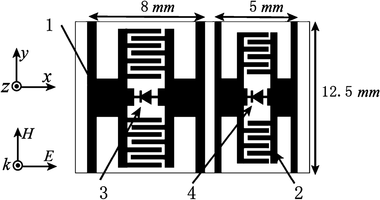
[0031] The size of the diffraction area plate used in the dual-frequency diffraction antenna in the present invention is 450mm×250mm, and 30 and 18 periodic artificial units are arranged corresponding to the x direction and the y direction, respectively. Such as figure 2 As shown, each periodic unit contains two H-shaped metal subunits of different sizes, the large-size subunit 1 and the small-size subunit 2, so in the x direction, the diffraction zone plate has a total of 60 subunits. A diode 3 is loaded in the large-size subunit 1 , and a diode 4 is loaded in the small-size subunit 2 .

[0032] In order to excite the corresponding electric resonance, the electric field polarization of the incident wave is in the x direction, and the magnetic field polarization is in the y direction. Two subunits of different sizes resonate at different frequencies. In order to independently adjust the resonant frequency of the two subunits, a varactor diode is loaded in the center of each...


PUM


Abstract

The invention discloses a dual-frequency diffraction antenna capable of independently scanning beams. The antenna comprises a feed source, a microwave dielectric plate having a sub-wavelength thickness and a plurality of periodic units arranged on the microwave dielectric plate, wherein each periodic unit comprises two H-shaped artificial subunit structures having different sizes. The H-shaped artificial subunit structure mainly consists of an interdigital metal electrode, two H-shaped metal electrodes respectively connected to two sides of the interdigital metal electrode and an electronic speed controller microwave diode arranged in the interdigital metal electrode; and the two H-shaped artificial subunit structures are individually adjustable electrical resonant structures with respective resonant frequency and transparent frequency. According to the special dispersion phenomenon of the artificial surface, the invention realizes a dual-frequency diffraction antenna capable of independently scanning beams, which has the advantages of simple structure, low cost and the like.

Description

technical field [0001] The invention belongs to the field of beam reconfigurable diffraction antennas, and discloses a dual-frequency diffraction antenna whose beams can be scanned independently. Background technique [0002] Diffraction is a basic physical phenomenon in electromagnetic waves, which has been widely used in beam focusing, beam splitting, beam collimation, microwave and optical beam scanning. Based on the principle of diffraction, typical diffraction devices include gratings and Fresnel diffraction zone plates. In the microwave field, diffractive zone plates have been used to design highly directional antennas and near-field focusing lenses. In recent years, in the millimeter-wave frequency band, based on the optical control semiconductor technology, the beam-scanning diffractive antenna has been experimentally confirmed. Light control semiconductor technology uses light intensity to realize the transparent and non-transparent control of semiconductor materi...

Claims


Application Information

Patent Timeline
Patent Type & Authority Applications(China)
IPC IPC(8): H01Q19/06H01Q15/02H01Q15/00H01Q13/06H01Q3/44H01Q5/20H01Q5/307
CPCH01Q3/446H01Q5/20H01Q5/307H01Q13/06H01Q15/0006H01Q15/02H01Q19/06
Inventor 李欢冉立新
Owner ZHEJIANG UNIV
Why Eureka
Try Eureka