Aero-engine compressor blade and machining method thereof

An aero-engine and processing method technology, which is applied in the field of aero-engines, can solve the problems of increasing the difficulty of polishing and manufacturing costs, unsatisfactory processing accuracy, and increased polishing allowance, so as to avoid fractures caused by internal stress concentration and reduce the difficulty of polishing and processing costs, reducing the effect of grinding steps

Active Publication Date: 2018-06-12
株洲丰发精工实业有限公司
View PDF4 Cites 15 Cited by
  • Summary
  • Abstract
  • Description
  • Claims
  • Application Information

AI Technical Summary

Problems solved by technology

[0003] The traditional machining method of aero-engine compressor blades is time-consuming and laborious, and the accuracy is difficult to guarantee. With the development of numerical control technology, most of the current compressor blades are manufactured by numerical control milling machines, but it is easy to cause machining stress and deformation, and the machining accuracy is still not ideal
[0004] When the current compressor blade is processed on a multi-axis machining center, due to the complex curved surface of the blade and the thin and large blade, it is unstable during the processing process, and it is forced to increase the polishing allowance, which increases the difficulty of polishing and the manufacturing cost.
[0005] With the continuous optimization of the machining process, the multi-axis machining center mainly depends on the NC program and tools, and the NC program is generated by the programming software through the 3D digital model of the blade. The key steps of 3D modeling are the data point accuracy of the blade, For the construction of each section curve and the modeling of the driving surface, due to the fact that the point data given by the designer has actual tolerance changes during the data collection process, there is an upper and lower tolerance between the actual collected data points and the theoretically designed data points. According to the actual collection The actual curve constructed by the data points formed the peaks and troughs, resulting in the wrinkled surface of the driving surface constructed by the curves of each section, which seriously affected the subsequent NC program compilation

Method used


Image

  • Aero-engine compressor blade and machining method thereof
  • Aero-engine compressor blade and machining method thereof

Examples


Embodiment

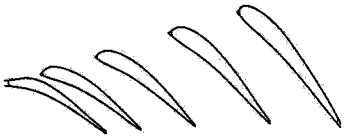
[0033] Such as figure 1 As shown in the compressor blade, the present embodiment provides a method for processing an aero-engine compressor blade, comprising the following steps:

[0034] S1. Three-dimensional measurement: According to the three-dimensional design drawing of the compressor blade, extract the crest points and trough points on the actual curves of each section to reconstruct a peak curve and trough curve; at the same time, construct the virtual curve of the blade body and tenon;

[0035] S2. Point cloud extraction: analyze the curvature of the actual curve, peak curve and trough curve in S1, and use the curvature of the actual curve as a reference to fine-tune the curvature of the peak curve and trough curve; construct a curve based on the obtained peak curve and trough curve midline;

[0036] S3. Surface reconstruction: constructing a grid surface from the midlines obtained from each section to generate a three-dimensional digital model of the blade;

[0037]...


PUM


Abstract

The invention belongs to the technical field of aero-engines, and discloses a compressor blade machining method. The compressor blade machining method includes the steps that step 1, three-dimensionalmeasurement is carried out, specifically, a crest curve and a trough curve are built by extracting actual curve crest points and trough points of cross sections according to a three-dimensional diagram of a compressor blade; virtual curves of a blade body and a jog are built; step 2, point cloud is extracted, specifically, curvatures of the actual curve, the crest curve and the trough curve of the step 1 are analyzed, and the curves of the crest curve and the trough curve are regulated according to actual curve curvatures; a center line is built according to the crest curve and the trough curve; step 3, a hook face is rebuilt, specifically, a mesh hook face is built with center lines of the cross sections to generate a three-dimensional digital model; step 4, procedures are regulated, specifically, the blade three-dimensional digital model is imported to a three-dimensional software and corrected compared with blade master body data scanned by the three-dimensional software; and step5, numerical control machining is carried out, specifically, numerical control programming is carried out according to the blade three-dimensional digital model of the step 4, and a blade is subjectedto numerical control milling with a ball end milling. According to the compressor blade machining method, the blade precision and the surface roughness of a compressor can be effectively ensured.

Description

technical field [0001] The invention relates to the technical field of aero-engines, in particular to an aero-engine compressor blade and a processing method thereof. Background technique [0002] Aeroengine compressor blade is one of the core components of the engine. The performance of the engine depends largely on the design and manufacturing level of the blade surface. The blade is a typical free-form surface part, and its surface shape and manufacturing accuracy are also directly Determines the size of the propulsion efficiency of the aero-engine. [0003] The traditional machining method of aeroengine compressor blades is time-consuming and laborious, and the accuracy is difficult to guarantee. With the development of numerical control technology, most of the current compressor blades are manufactured by numerical control milling machines, but it is easy to cause machining stress and deformation, and the machining accuracy is still not ideal. [0004] When the current...

Claims


Application Information

Patent Timeline
Patent Type & Authority Applications(China)
IPC IPC(8): B23P15/02
Inventor 苏文宏袁昌华向侠
Owner 株洲丰发精工实业有限公司
Why Eureka
Try Eureka