Cross detection system and method of motor rotor position

A motor rotor and cross detection technology, which is applied in the estimation/correction of motor parameters, etc., can solve problems such as runaway time, high amplitude of injected signals, loss, etc., and achieve the effect of improving reliability

Pending Publication Date: 2018-06-15
江西精骏电控技术有限公司
View PDF0 Cites 0 Cited by
  • Summary
  • Abstract
  • Description
  • Claims
  • Application Information

AI Technical Summary

Problems solved by technology

One is the modified PWM test pulse excitation method. This method uses the high-frequency impedance (electrical saliency and mechanical saliency) of the motor to be excited to obtain a feedback signal to measure the position of the rotor. However, the drive motor has low inductance, and the measurement stage is not Control current will cause runaway time
Another type is the high-frequency signal injection method. This method injects a balanced high-frequency signal into the stator windi

Method used


Image

  • Cross detection system and method of motor rotor position

Examples


Embodiment Construction

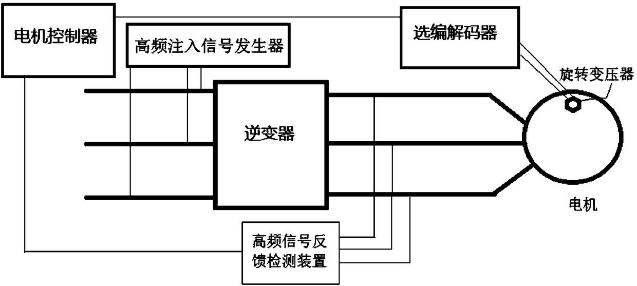
[0022] Such as figure 1 The cross-detection system for the rotor position of the motor shown includes a motor, a resolver, a codec, a motor controller, a high-frequency signal generator, an inverter, a wiring harness, and a high-frequency signal feedback detection device.

[0023] The motor is a permanent magnet drive motor, mainly composed of a base, a rotor and a stator.

[0024] A resolver is an induction micromotor whose output voltage maintains a certain functional relationship with the rotor angle.

[0025] The optional codec is a device that decodes the output voltage of the resolver into the angular position of the rotor according to the functional relationship between the output voltage of the resolver and the rotor angle.

[0026] The motor controller is a device that controls the output parameters of the motor according to the motor output requirements of the vehicle controller. In order to control the rotation output of the motor, the motor controller needs accur...


PUM


Abstract

The invention discloses a cross detection system of motor rotor position. The cross detection system of motor rotor position is characterized in that a power supply input terminal of a motor is connected with a power supply through an inverter; the motor includes a support, a rotor and a stator; a motor controller controls the output parameters of the motor; a rotary transformer is fixed on the motor; the rotary transformer outputs an induction signal to a selection decoder; the selection decoder outputs a rotor position signal to the motor controller; a high frequency injection signal-generator respectively sends a signal to each phase of the input terminal of the inverter; a high frequency signal feedback detector is connected with each phase of the output terminal of the inverter, and separates a feedback signal from an injection signal; and the high frequency signal feedback detector outputs the rotor position signal to the motor controller. The cross detection system of motor rotor position has the advantages of being able to improve the motor driving reliability by performing cross detection on double path of rotor positions, and providing a fault driving mode so as to avoidthe situation that the electric vehicle needs a trailer because the rotary transformer fails.

Description

technical field [0001] The invention relates to the field of motor detection, in particular to a cross detection system for the rotor position of a high-reliability permanent magnet synchronous motor used in new energy vehicles. Background technique [0002] Electric vehicles, including pure electric vehicles and hybrid electric vehicles, have electric drive systems. The electric drive system generally consists of a DC power supply (such as a lithium power battery system), a power inverter, a motor, and the necessary control system. [0003] Most modern high-performance electric motors use field-oriented control (FOC) or "vector" control, which requires precise measurement of the angular position of the rotor. In the prior art, the position of the rotor angle is usually measured by a position sensor such as a resolver. However, in the prior art, the resolver is the most easily damaged part of the motor. Once the resolver or other position sensors are damaged, if the motor ...

Claims


Application Information

Patent Timeline
IPC IPC(8): H02P23/14
CPCH02P23/14
Inventor 王长江王世强许年昌
Owner 江西精骏电控技术有限公司
Why Eureka
Try Eureka