Artificial chordae implantation system provided with detection device

A technology of artificial chordae and detection device, which is applied in the field of artificial chordae implantation system, can solve the problems of high production cost and operation cost, complex production process, and cumbersome device structure, and achieve economic burden reduction, simple device structure, and easy operation. convenient effect

Active Publication Date: 2018-06-22
HANGZHOU VALGEN MEDTECH CO LTD
View PDF6 Cites 24 Cited by
  • Summary
  • Abstract
  • Description
  • Claims
  • Application Information

AI Technical Summary

Problems solved by technology

The artificial chord implantation device uses optical fibers in interventional therapy devices, resulting in a complex structure of the device, and the optical fiber needs to enter the patient's body with the device body, which increases the risk of surgery
In addition, since the capture verification system needs to be equipped with a capture verification monitor, the device structure is complicated, the production process is complicated, and the production cost and operation cost are high.

Method used


Image

  • Artificial chordae implantation system provided with detection device
  • Artificial chordae implantation system provided with detection device
  • Artificial chordae implantation system provided with detection device

Examples


Embodiment 1

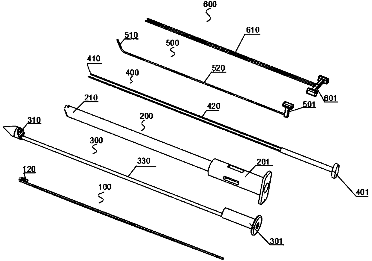
[0070] like Figure 3 to Figure 36 As shown, an artificial chord implantation system with a detection device is used to implant the artificial chord into the patient's body to replace the diseased or broken chord in the patient's heart. The artificial chord implantation system includes a clamping device 300 , a puncture device 400 , a pushing device 200 and a detection device 600 . The pushing device 200 includes a pushing catheter 210 . The clamping device 300 includes a clamping push rod 330 accommodating the artificial chordae 100 , and a distal clamp 310 and a proximal clamp 320 for cooperating to clamp the leaflet. The distal chuck 310 is disposed at the distal end of the clamping push rod 330 . The proximal collet 320 is disposed at the distal end of the pushing catheter 210 . The piercing device 400 and the clamping push rod 330 are movably installed in the pushing catheter 210 respectively. The detecting device 600 includes at least one probe 610 , and the probe 61...

Embodiment 2

[0122] The artificial chord implantation system with detection device in Embodiment 2 has basically the same structure as the artificial chord implantation system in Embodiment 1. The difference is that in the artificial chord implantation system in Embodiment 2, the detection device 600 The two probes 610 are arranged side by side and the distal ends of the two probes 610 are connected.

[0123] see Figure 37 to Figure 39, the distal end of the probe 610 has certain elasticity / toughness, and is connected together by a connecting rod 620 . When the detection handle 601 is retracted, the connecting rod 620 is placed on the clamping surface of the proximal chuck 320 . The clamping surface of the proximal chuck 320 is preferably provided with a groove 323 for accommodating the connecting rod 620 , and the groove 323 should communicate with the probe channel 270 . Correspondingly, the clamping surface of the distal chuck 310 is also provided with a connecting rod receiving groo...

Embodiment 3

[0127] The artificial chord implantation system with detection device in Embodiment 3 is basically the same in structure as the artificial chord implantation system in Embodiment 1. The difference is that in the artificial chord implantation system in Embodiment 3, the detection device 600 The probe 610 is movably mounted in the clamping push rod 330 .

[0128] Specifically, see Figure 41 and Figure 42 , the probe 610 is installed in the clamping push rod 330 , and the clamping push rod 330 is installed in the pushing catheter 210 , that is, the probe 610 is also located in the lumen of the clamping push rod 330 . The distal end of the probe 610 is bent proximally and accommodated in the distal chuck 310 . The clamping surface of the distal clamp 310 is provided with a probe outlet 318 , and the clamping surface of the corresponding proximal clamp 320 is provided with a probe receiving cavity 324 opposite to the probe outlet 318 .

[0129] A curved probe bend 319 is set i...


PUM


Abstract

The invention discloses an artificial chordae implantation system provided with a detection device. The artificial chordae implantation system comprises a clamping device, a puncture device, a push device and a detection device, wherein the push device comprises a push catheter; the clamping device comprises a clamping push rod in which an artificial chordae is accommodated as well as a distal clamping head and a proximal clamping head which are cooperated for clamping a valve leaflet; the detection device comprises at least one probe; the probe is movably inserted into the push catheter; a detection outlet is kept in the clamping surface of the proximal clamping head or the distal clamping head, and correspondingly, a probe accommodating cavity, which is opposite to the probe outlet, is kept in the clamping surface of the distal clamping head or the proximal clamping head; and the distal end of the probe is accommodated in the probe accommodating cavity from the probe outlet when thedistal clamping head and the proximal clamping head are closed. According to the artificial chordae implantation system provided by the invention, it can rapidly and accurately detect whether the valve leaflet is clamped between the distal clamping head and the proximal clamping head or not via the detection device of a mechanical structure; the system is simple in structure, simple and convenientto operate and low in surgical risk; and the system can reduce production cost of apparatuses and reduce economic burdens of patients.

Description

technical field [0001] The invention belongs to the technical field of medical devices, and relates to a device for repairing heart valve defects, in particular to an artificial chord implantation system with a detection device. Background technique [0002] The mitral valve is a one-way "valve" between the left atrium (abbreviation: LA) and the left ventricle (abbreviation: LV), which can ensure blood flow from the left atrium to the left ventricle. See figure 1 , a normal healthy mitral valve has multiple chordae. The leaflets of the mitral valve are divided into anterior leaflet and posterior leaflet. When the left ventricle is in a diastolic state, the two are in an open state, and blood flows from the left atrium to the left ventricle; when the left ventricle is in a systolic state, the chordae are stretched to ensure The valve leaflets will not be rushed to the atrium side by the blood flow, and the front and rear leaflets are well closed, thereby ensuring that blood...

Claims


Application Information

Patent Timeline
Patent Type & Authority Applications(China)
IPC IPC(8): A61F2/24
CPCA61F2/2457A61F2/2466A61B17/0469A61B2017/0472A61B17/0482A61B2017/00858A61B2017/0495A61B2017/00243A61F2002/3008A61F2002/4622A61B17/3468A61B2017/3425A61B2017/00862A61B2017/3445A61B5/06A61B2017/3488
Inventor 张庭超张伟伟周春远
Owner HANGZHOU VALGEN MEDTECH CO LTD
Why Eureka
Try Eureka