
Ground reinforcement equipment and deep ground treatment methods

A foundation reinforcement and equipment technology, applied in excavation, soil protection, infrastructure engineering, etc., can solve the problems of difficult crane position adjustment and low efficiency, and achieve the effect of improving work efficiency and stability

Active Publication Date: 2019-11-19
浙江立鹏建设有限公司
View PDF6 Cites 0 Cited by
  • Summary
  • Abstract
  • Description
  • Claims
  • Application Information

AI Technical Summary

Problems solved by technology

[0005] The current dynamic compaction method is to use a crane to lift the weight to a high altitude. In order to ensure the stability of the crane, a support frame will be installed at the cantilever of the crane to support the cantilever. Therefore, if it is necessary to adjust the tamping point, the position of the crane It is difficult to adjust and the efficiency is low, so there is a need for a method that can easily reinforce the deep foundation while ensuring the firmness of the foundation

Method used


Image

  • Ground reinforcement equipment and deep ground treatment methods
  • Ground reinforcement equipment and deep ground treatment methods
  • Ground reinforcement equipment and deep ground treatment methods

Examples


Embodiment 1

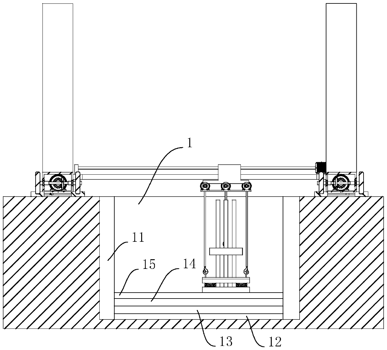
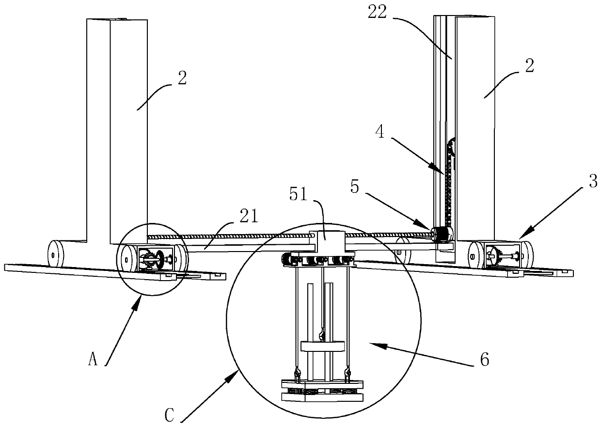
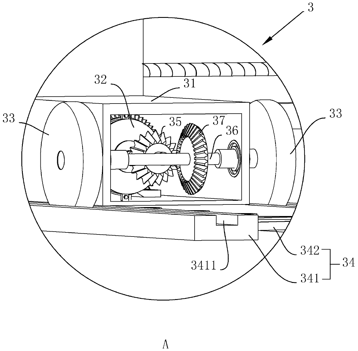
[0055] A kind of ground reinforcement equipment is disclosed, such as figure 1 , 2 As shown, a ground reinforcement equipment formed by a deep foundation treatment method includes two fixed frames 2, a slide rail 21 horizontally installed between the two fixed frames 2, and a sliding block movably sleeved on the slide rails 21 51. The two fixing frames 2 are respectively fixedly installed on the ground surface on both sides of the deep foundation pit 1. There are displacement components 3 for lateral movement on both sides of the bottom of each fixing frame 2. Lifting grooves are provided on the opposite surface of each fixing frame 2. 22 and a lifting mechanism 4 for moving the slide rail 21 up and down in the lifting groove 22; the slide rail 21 is also provided with a drive assembly 5 for controlling the sliding block 51 to move along the length direction of the slide rail 21, and the sliding block 51 A tamping assembly 6 for tamping deep foundations is connected below.

...

Embodiment 2

[0070] Such as figure 1 As shown, a deep foundation processing method includes the following steps:

[0071] S1: Set the excavation sideline on the ground surface and excavate the foundation pit according to the sideline;

[0072] S2: When the foundation pit is excavated to a depth of about 1.5m, arrange reticulated reinforcement on the side wall of the foundation pit and pour cement on the side wall to cover the reticulated rebar to form a cement wall 11, the cement wall 11 can The effect of waterproof and anti-seepage;

[0073] S3: Repeat S1 and S2 to make it a deep foundation pit 1 with a depth greater than 5m;

[0074] S4: Sprinkle a layer of desiccant 12 on the foundation, the desiccant 12 is preferably lime powder, the thickness is preferably 2mm, and is mainly used to absorb moisture in the foundation;

[0075] S5: After the foundation is dry, pour a layer of caulking agent 13 on the foundation. The caulking agent 13 is preferably crack filling glue, which is used to...


PUM


Abstract

The invention discloses a deep layer foundation treatment method and foundation strengthening equipment formed through the method, and belongs to the field of foundation treatment. The problem that according to an existing dynamic consolidation method, a deep layer foundation is not pounded conveniently is solved. According to the technical scheme, the deep layer foundation treatment method and the foundation strengthening equipment formed through the method are characterized in that a drying agent, a gap filling agent, a water passing expansion rubber layer and a rubble layer are sequentiallyadded in the deep layer foundation, and finally the foundation strengthening equipment is used for conducting strengthening treatment on the deep layer foundation. The deep layer foundation treatmentmethod and the foundation strengthening equipment formed through the method have the beneficial effects that the firmness and the cost performance of the deep layer foundation are high.

Description

technical field [0001] The invention relates to a treatment method for foundations, in particular to foundation reinforcement equipment and a treatment method for deep foundations. Background technique [0002] my country has a vast territory, and there are soft soil layers of various origins, especially in coastal cities, whose soil quality has the characteristics of high water content, large void ratio, low shear strength, and high compressibility, so when excavating deep foundations in coastal cities, it is best The firmness of the foundation should be considered. [0003] At present, there are many ground treatment methods at home and abroad, and the main ground treatment methods include: filling method, preloading method, dynamic compaction method, deep mixing method, etc. The mechanisms of these ground treatment methods are different, and in the process of continuous development, each ground treatment method has its own scope of use and certain limitations. Among them...

Claims


Application Information

Patent Timeline
Patent Type & Authority Patents(China)
IPC IPC(8): E02D3/054E02D17/02E02D17/04E02D5/18E02D31/02E02D31/04
CPCE02D3/054E02D5/18E02D17/02E02D17/04E02D31/02E02D31/04
Inventor 朱小平郑伟
Owner 浙江立鹏建设有限公司
Learn More