Thermal fatigue testing system for ceramic-based composite material structural part

A composite material and test system technology, applied in the field of ceramic matrix composite material test, can solve the problems of high cost, high cost, large pollution, etc., and achieve the effect of low cost, fast cooling speed and uniform cooling

Active Publication Date: 2018-06-22
BEIHANG UNIV
View PDF6 Cites 18 Cited by
  • Summary
  • Abstract
  • Description
  • Claims
  • Application Information

AI Technical Summary

Problems solved by technology

However, the high-temperature box-type resistance furnace can only provide a uniform temperature field, and the furnace of the high-temperature electric furnace is closed, so it is impossible to cool the test piece locally by cooling air, and it is not convenient to measure the temperature and observe the test process in real time
[0008] (2) Flame heating: Flame heating can provide a higher temperature for the test piece, but it cannot precisely control

Method used


Image

  • Thermal fatigue testing system for ceramic-based composite material structural part

Examples


Embodiment Construction

[0043] In order to understand the above-mentioned purpose, features and advantages of the present invention more clearly, the present invention will be further described in detail below in conjunction with the accompanying drawings and specific embodiments. It should be noted that, in the case of no conflict, the embodiments of the present application and the features in the embodiments can be combined with each other.

[0044] In the following description, many specific details are set forth in order to fully understand the present invention. However, the present invention can also be implemented in other ways different from those described here. Therefore, the protection scope of the present invention is not limited by the specific details disclosed below. EXAMPLE LIMITATIONS.

[0045] The present invention will be further described in detail with reference to the accompanying drawings and embodiments.

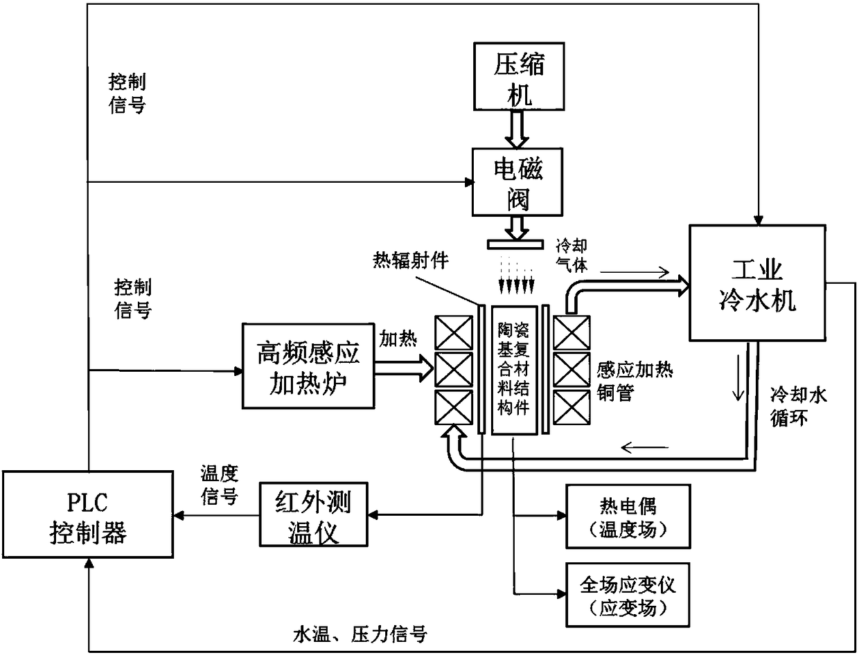
[0046] figure 1 It is a structural diagram of the thermal fatigue tes...


PUM

PropertyMeasurementUnit
Outer diameteraaaaaaaaaa
Tube wall thicknessaaaaaaaaaa
Coefficient of linear expansionaaaaaaaaaa

Abstract

The invention discloses a thermal fatigue testing system for a ceramic-based composite material structural part. The system comprises a thermal radiation part and a high-frequency sensitive heating furnace, wherein the high-frequency sensitive heating furnace comprises a sensitive heating copper tube which is arranged around the thermal radiation part, an industrial cooling water machine, an air compressor, a PLC (Programmed Logic Controller), a temperature measuring device and a full-field strain gauge. By adopting the technical scheme of the invention, the ceramic-based composite material structural part is indirectly heated through high-frequency sensitivity, and the heating speed, the heat-preservation temperature and the cooling time of the testing process are automatically controlled.

Description

technical field [0001] The invention relates to a thermal fatigue test system for ceramic matrix composite material structural parts, belonging to the technical field of ceramic matrix composite material testing. Background technique [0002] Ceramic materials have many advantages such as high temperature resistance, low density, corrosion resistance and high hardness. But its brittleness is an important shortcoming that restricts the popularization and application of structural ceramic materials. Researchers have conducted extensive research on ceramic toughening methods. The current common toughening methods include short fiber reinforcement (whisker reinforcement), layered toughening and continuous fiber toughening. Commonly used toughening fibers include glass fibers, high modulus carbon fibers, silicon carbide fibers, alumina fibers, etc. The toughened ceramic matrix composite (CMC) has higher reliability and is less prone to brittle fracture. [0003] In aero-engin...

Claims


Application Information

Patent Timeline
IPC IPC(8): G01N3/60
CPCG01N3/60
Inventor 申秀丽乔逸飞李鹏
Owner BEIHANG UNIV
Why Eureka
Try Eureka