
Distributed all-optical voltage measuring system and measuring method implemented by same

A voltage measurement and distributed technology, which is used in the measurement of electrical variables, non-electrical signal transmission systems, measurement devices, etc. It can solve the problems of large quantity and other problems, so as to achieve the effect of strong anti-electromagnetic interference ability, improving reliability and stability, and strong anti-electromagnetic interference ability.

Inactive Publication Date: 2018-06-22
CHONGQING UNIV
View PDF5 Cites 7 Cited by
  • Summary
  • Abstract
  • Description
  • Claims
  • Application Information

AI Technical Summary

Problems solved by technology

At present, there are many difficulties in realizing the distributed overvoltage voltage sensing of long-distance transmission lines. Most of the existing voltage sensing devices need to install power supply units at the measurement points, and their working reliability cannot be guaranteed in the wild or in harsh environments. ; At the same time, the amount of single voltage data collection is too large, the use of wireless transmission is not only costly, but once the signal is missing, the data transmission cannot be completed
In addition, due to the limitation of the physical characteristics of the sensor, even if the existing division multiplexing technology still needs to use multiple optical fibers, it is difficult to achieve multi-point distributed voltage acquisition.

Method used


Image

  • Distributed all-optical voltage measuring system and measuring method implemented by same
  • Distributed all-optical voltage measuring system and measuring method implemented by same
  • Distributed all-optical voltage measuring system and measuring method implemented by same

Examples


Embodiment Construction

[0056] The present invention will be further described below in conjunction with drawings and embodiments.

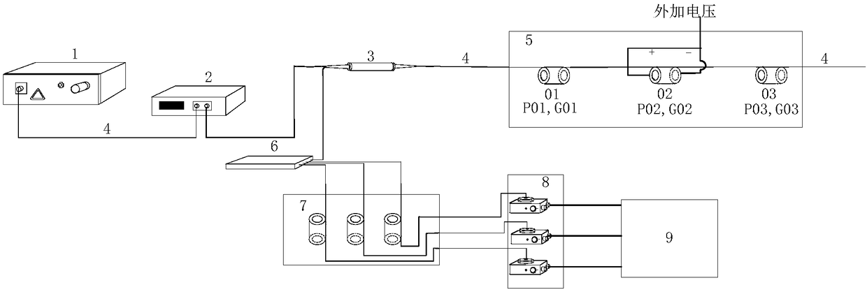
[0057] see figure 1 , the distributed voltage measurement system of this embodiment includes a broadband laser light source 1, an optical amplifier 2, an optical circulator 3, a transmission fiber 4, a voltage sensing system 5, an optical splitter 6, an optical selection system 7, a photoelectric conversion system 8, Terminal signal display processing system 9 . Except for the cable connection between the photoelectric conversion system 8 and the terminal signal display processing system 9, the transmission optical fiber 4 is used to connect the 1-8 parts of the distributed voltage measurement system. The broadband laser light source 1 outputs laser light within a certain wavelength range, the optical signal is sent to the optical amplifier 2 through the transmission fiber 4, and then enters the optical circulator 3, and the optical signal is sent to the voltage sensin...


PUM


Abstract

The invention discloses a distributed all-optical voltage measuring system and a measuring method implemented by the same. The distributed all-optical voltage measuring system comprises a broadband laser light source, a light amplifier, a light circulator, a transmission fiber, a voltage sensing system, a light splitter, a light selection system, a photoelectric conversion system and an end signaldisplay and processing system. Laser light in certain wavelength ranges can be outputted by the broadband laser light source, power of the light source can be amplified by the light amplifier, amplified light signals can be transmitted into various sensor input ends of the sensing system by the transmission fiber, light signals can be fed by various sensors and can be screened by the light selection system, the light signals fed by the sensors with voltage change can be changed and can be outputted by corresponding channels of the light selection system, output light intensity signals can beconverted into voltage signals by photoelectric detectors, and additional voltage numerical values measured by circuits can be acquired by the aid of the end signal display and processing system. Thedistributed all-optical voltage measuring system and the measuring method have the advantages of passivity, high electromagnetic interference resistance, broad response frequency band and good power frequency response.

Description

technical field [0001] The invention relates to the technical field of power detection, in particular to a distributed all-photovoltage measurement system and a measurement method thereof. Background technique [0002] Real-time measurement of grid voltage is of great significance for system protection, line fault monitoring and measurement. At present, there are many difficulties in realizing the distributed overvoltage voltage sensing of long-distance transmission lines. Most of the existing voltage sensing devices need to install power supply units at the measurement points, and their working reliability cannot be guaranteed in the wild or in harsh environments. ; At the same time, the amount of single voltage data collection is too large, and the use of wireless transmission is not only costly, but once the signal is lost, the data transmission cannot be completed. In addition, due to the limitation of the physical characteristics of the sensor, even if the existing mul...

Claims


Application Information

Patent Timeline
IPC IPC(8): G01R19/00G08C23/06
CPCG01R19/00G08C23/06
Inventor 杨庆何彦霄孙尚鹏司马文霞袁涛杨鸣孙魄韬韩睿罗曼丹
Owner CHONGQING UNIV
Learn More