Small turbojet engine adopting self-acting air bearing and rotor support structure

A turbojet engine and supporting structure technology, applied in the directions of engine components, engine lubrication, turbine/propulsion lubrication, etc., can solve the problems of temperature not exceeding 180 ° C, not exceeding 30 hours, expensive maintenance, etc., to achieve production The effect of the same cost, lower operating temperature and low maintenance cost

Active Publication Date: 2018-06-29
中科航星科技股份有限公司
View PDF6 Cites 8 Cited by
  • Summary
  • Abstract
  • Description
  • Claims
  • Application Information

AI Technical Summary

Problems solved by technology

Since the birth of the turbojet engine for hundreds of years, the oil-lubricated rolling bearing system has always played a vital role, but it has limited the development of the engine to a certain extent: (1) The temperature of the lubricating oil cannot exceed 180 °C, and it is necessary to increase the lubrication A series of accessories such as oil pump, oil-gas separator, oil cooler and oil filter; (2) The rolling bearing is affected by centrifugal force and cannot make the engine work at a higher speed, and the DN value can exceed 2×10 6 (3) The oil-lubricated bearing system accounts for 10% to 30% of the cost and weight of the engine, and 25% to 50% of the maintenance volume, requiring a lot of time-consuming, laborious and expensive maintenance to ensure flight safety; (4) For the small turbojet engine with 0-2-0 rotor structure, which is currently the mainstream in the world, the life of the rolling bearing used is generally not more than 30 hours, which has become the most critical factor restricting the service life of the engine

Method used


Image

  • Small turbojet engine adopting self-acting air bearing and rotor support structure
  • Small turbojet engine adopting self-acting air bearing and rotor support structure
  • Small turbojet engine adopting self-acting air bearing and rotor support structure

Examples


Embodiment Construction

[0027] The present invention will be further described in detail below in conjunction with the examples, the following examples are explanations of the present invention and the present invention is not limited to the following examples.

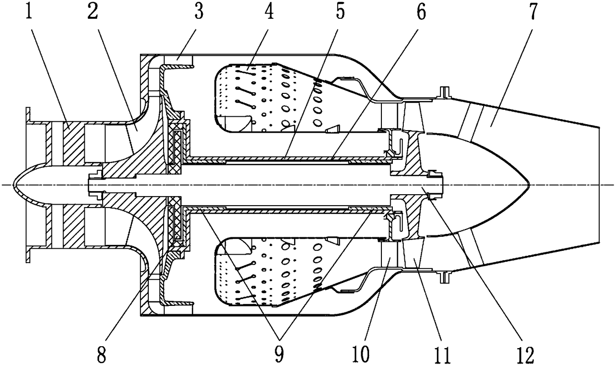
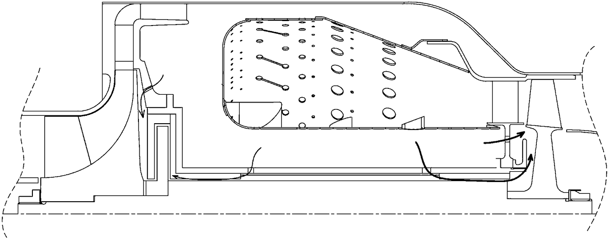
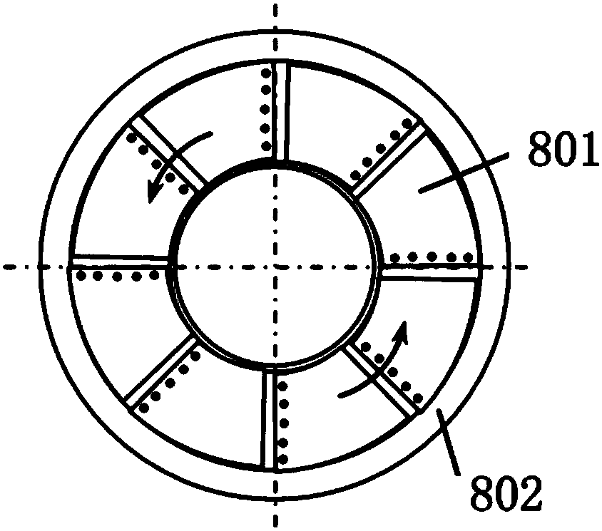
[0028] Such as figure 1 , 2As shown, the engine rotor support structure of this embodiment is suitable for small turbojet engines, and uses dynamic pressure air bearings to support the engine rotor system, including compressor casing 1, centrifugal impeller 2, diffuser 3, combustion chamber 4, bearing support Seat 5, spacer ring 6, tail nozzle 7, axial thrust bearing 8, radial bearing 9, guider 10, turbine rotor 11, central shaft 12. Among them, the centrifugal impeller 2 is arranged at the front end of the central shaft 12, the turbine rotor 11 is arranged at the rear end of the central shaft 12, and the front and rear radial bearings 9 are installed between the bearing support 5 and the central shaft 12 to bear the diameter of the rotor. ...


PUM


Abstract

The invention discloses a small turbojet engine adopting a self-acting air bearing. The small turbojet engine adopting self-acting air bearing is adopted as engine rotor support, gas of an engine serves as a lubricant and bears the dynamic pressure load, and gas supply of an outer gas source is not needed. According to the characteristics of the engine, the radial bearing assembly coaxiality is ensured, and the rotor and stator gap is controlled within a reasonable range so as to avoid collision and rubbing. The axial load of the rotor is lowered by adjusting the layout of a secondary air flowchannel so as to meet the requirement of a thrust bearing, the work temperature of the bearing is lowered effectively, and life of the bearing is prolonged. According to the small turbojet engine, structural complexity and machining cost of the turbojet engine are not increased, compared with a traditional rolling bearing engine, the mall turbojet engine has the advantages of being good in adaptivity and impact resistance, high in stability, free of a special lubrication and cooling system and low in maintenance cost, thus the total oil consumption rate of the engine is lowered, weight is reduced, the life of the engine is prolonged substantially, and positive significance is achieved for the aerodynamic field.

Description

technical field [0001] The invention relates to the field of aero-engines, and more specifically relates to a small turbojet engine and its rotor support structure using a dynamic pressure air bearing, and is especially suitable for small high-altitude long-endurance unmanned aerial vehicles and their power devices. Background technique [0002] Due to its small size and light weight, small turbojet engines (thrust less than 200 kg) are suitable for high-altitude and high-speed flight, and are widely used as power for small and medium-sized UAVs, target drones and reconnaissance drones, and can also be used for tactical cruise missile power. Since the birth of the turbojet engine for hundreds of years, the oil-lubricated rolling bearing system has always played a vital role, but it has limited the development of the engine to a certain extent: (1) The temperature of the lubricating oil cannot exceed 180 °C, and it is necessary to increase the lubrication A series of accesso...

Claims


Application Information

Patent Timeline
Patent Type & Authority Applications(China)
IPC IPC(8): F02C7/06
Inventor 龚建波张坤郭磊黄恩亮苏尚美徐纲朱俊强
Owner 中科航星科技股份有限公司
Why Eureka
Try Eureka